Programming Instructions 60
RNS
®
System User Manual
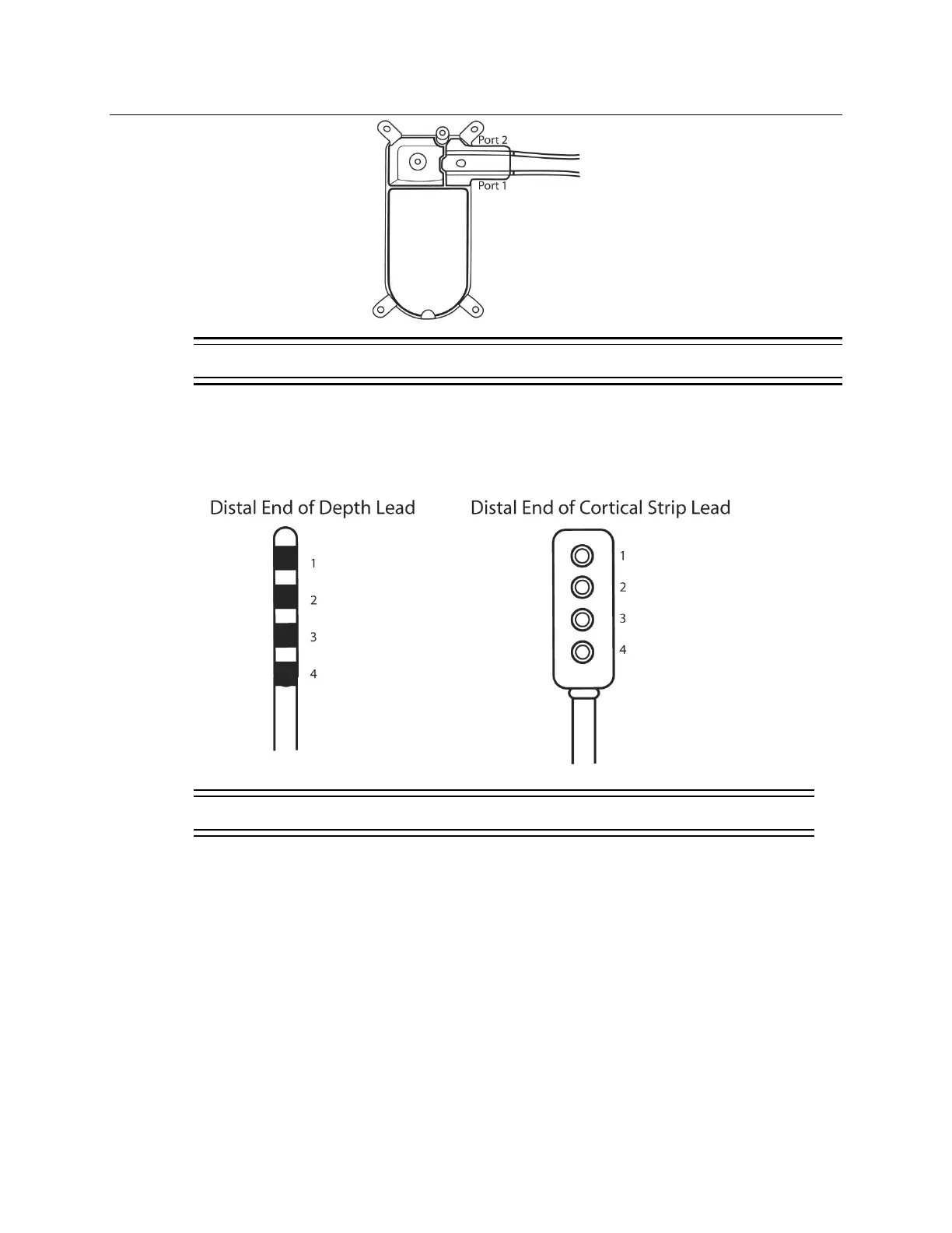
Figure 19: RNS
®
Neurostimulator port #1 and #2 locations. Port #1 is located towards the center of the
neurostimulator and port #2 is closer to the edge.
Note: Additional leads implanted may be recorded in the comments field.
3. Assign a distinctive label identifying each lead; otherwise a generic L
EAD LABEL is assigned
automatically. Electrode numbers (1- 4) are assigned automatically.
Figure 20: For both the depth lead and cortical strip lead, electrodes are numbered 1 through 4. Electrode 1 is
the most distal.
 Loading...