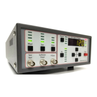
4
The Model 3501 Optical Chopper is designed to interrupt light paths in optical
experiments at frequencies from 4 Hz to 6.4 kHz. Both single and dual beam
experiments can be performed across a broad range of chopping frequencies.
The chopper has a crystal controlled frequency synthesizer that serves as an
internal reference frequency for locking the chopper to a particular chopping
frequency. Reference frequencies can also be provided through the Sync Input
to allow the chopper to lock to an external source. A block diagram of the
optical chopper system is shown in Figure 1.
Several measures ensure that jitter and drift of the chopping frequency is
reduced to a minimum. Precision photo-etched wheels are mounted on a
high quality DC motor. The motor head has a photo-sensor for monitoring
the chopping frequency of the outer part of the wheel (F
outer
). The chopper
controller then actively stabilizes the motor speed to match the desired chop-
ping frequency. This technique minimizes phase noise at the chopping fre-
quency and provides for long-term stable chopping with a minimum of fre-
quency drift.
Figure 1 shows a block diagram of the Model 3501 Optical Chopper system.
Programmable divide/multiply circuitry allows for harmonic or subharmonic
locking of the chopper to the reference frequency. In addition, the phase of
the chopping frequency may be varied over a -180 to +179 degree range with
respect to the reference frequency. A variety of TTL level outputs are available
for use in triggering lock-in amplifiers, oscilloscopes, photon counters or box-
car averagers.
II
Introduction
Artisan Technology Group - Quality Instrumentation ... Guaranteed | (888) 88-SOURCE | www.artisantg.com