5
The chopping frequency, as well as a number of other operating parameters,
can be viewed on the front panel display, and cursor keys provide easy adjust-
ment of operating parameters. From the front panel the user can store and
recall up to nine instrument set-ups. An IEEE-488 interface provides remote
operation of all instrument functions.
The chopper head can be mounted on a 1/2”-diameter post or bolted directly
to a standard optical bench. The Model 3501 Optical Chopper is supplied with
four chopper wheels and a wheel cover. The Model 3510 Rack Mount Kit, an
accessory that is sold separately, enables the chopper controller to be mounted
in a rack (see Page 21).
Optical Trigger
Motor
Chopping Head
Phase
Shifter
Ext V
4 Hz - 6.4 KHz
Micro-
processor
Front
Panel
+/-
H/S
Norm
Out 1
Out 2
f Outer
f Synch
f Outer
Out 1
Out 2
Synch
Out
Int
Synch In
Subharmonic
Divide by 1 to 15
Internal Frequency
Synthesizer
Harmonic
Multiplier 1 to 15
Motor
Controller
Divide by 7
Divide by 6
IEEE-488
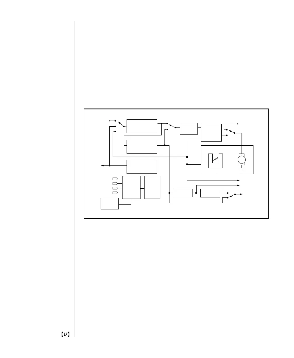
Fig. 1
Block diagram of the Model 3501 Optical Chopper.
Artisan Technology Group - Quality Instrumentation ... Guaranteed | (888) 88-SOURCE | www.artisantg.com