Getting Started LB1005 Operating Manual
8 Revision 1 Bookham
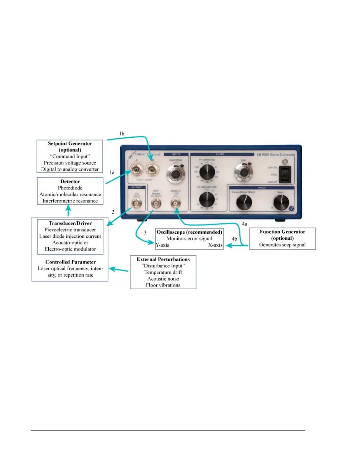
The input section of the LB1005 is a high-impedance, differential amplifier
stage that offers flexibility in interfacing to many types of detector outputs.
The A and -B inputs can be used together with differential signals to remove
common-mode noise and systematics. Single-ended signals can also be
connected, as shown by connection 1a, by simply leaving the unused channel
unconnected, or, as depicted by connection 1b, by attaching a stable voltage
source that generates an external setpoint voltage. Alternatively, the Input
Offset knob can provide DC offset to the detector signals. To invert either
differential or single-ended signals, reverse the A & -B connections.
Figure 3: Typical signal connections for LB1005
2. LB1005 Output to transducer input: To close the feedback loop, an
electrically tuned transducer is necessary for varying the controlled
parameter. For example, a piezoelectric transducer (PZT) to which a cavity
mirror is mounted can tune the wavelength of a laser. Typically, the output
of the LB1005 does not interface with the transducer directly but instead
provides the input to an amplifier system that conditions the control signal to
properly drive the transducer. For the PZT discussed above, the control
signal from the LB1005 Output will usually feed a high-voltage amplifier that
connects to the PZT. Be careful not to exceed any input voltage limits of the
transducer. If necessary, the Output voltage of the LB1005 can be limited by