LB1005 Operating Manual Getting Started
Bookham Revision 1 9
setting the Output Voltage Limit trimpots located on the rear panel. See
section Setting Output Voltage Limits in Chapter 3 for more details.
3. LB1005 Error Monitor output to oscilloscope: The Error Monitor allows the
user to view the actual error signal that is being processed by the P-I filter.
Since integral feedback forces the error signal to zero voltage, the parameter
that is being controlled will assume whatever value corresponds to zero error
(equal to zero volts). Observing the Error Monitor enables the user to adjust
offsets so that the locking point corresponds to the desired value of the
controlled parameter. The error signal is also an excellent diagnostic for
monitoring the lock condition and optimizing the feedback gain. Because the
time domain behavior of the error signal is so important to understanding the
feedback control, viewing the Error Monitor output on an oscilloscope is
highly recommended.
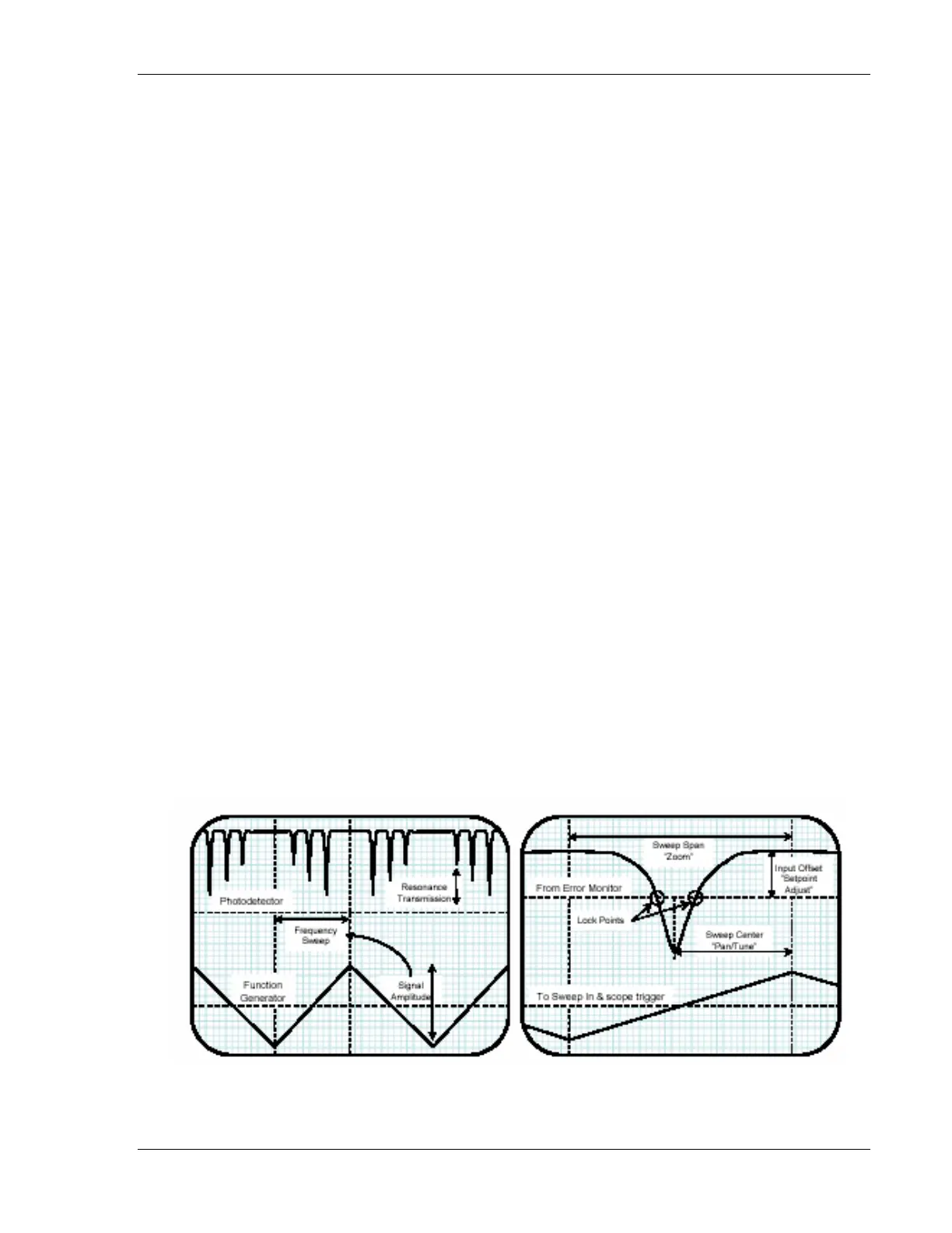
4. Function generator output to LB1005 Sweep In: For detector signals that are
derived from optical resonances, it is convenient to sweep the transducer so
that the optical frequency scans over the resonance. Observing the resonance
on an oscilloscope often makes it easier to offset the error signal so that the
locking point (at zero volts) aligns with the desired optical frequency (see
Figure 4 below for an example). Furthermore, sweeping the transducer helps
to locate the resonance and place the optical frequency within the locking
range of the servo system. To add sweep capability, connect a low-frequency
(30—60 Hz is usually sufficient) triangle waveform from a function generator
to the Sweep In connector, as shown by connection 4a. The sweep signal will
then be output to the transducer, with its amplitude controlled by the Sweep
Span knob. To synchronize the sweep with the Error Monitor signal, also
connect the function generator output to the oscilloscope’s timebase trigger,
shown by connection 4b.
Figure 4: Typical oscilloscope signals are shown for locking to the side of an optical
resonance. The dashed horizontal lines indicate ground for denoted signals. a) A triangle