6.REPLACINGPARTS
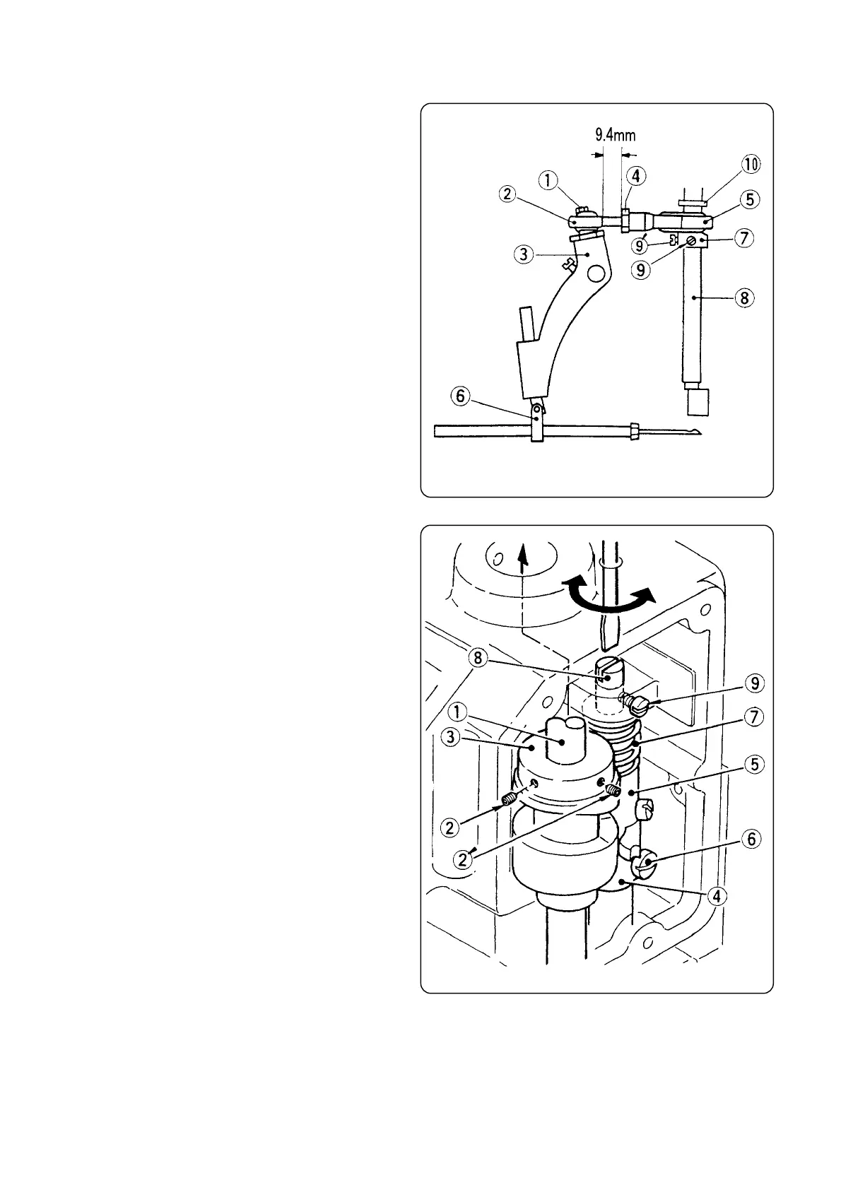
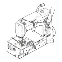
ForreplacementoradjustmentofBallRod,refertoFig.13.
TakeoutScrew①anddisconnectRodEnd② from
NeedleBarLever ③.AfterlooseningtheNut ④,adjustthe
clearancebetweenConnectingRod ⑤ andRodEnd ②,so
thatNeedleBarmovesinthecenteroftheclearance
betweentheupperandlowerPresserBarBushings.(Needle
Barstrokeis37mm).
TofixEccentricCam⑦onMainShaft⑧,tightenthe
Screw⑨and⑨ʼonMainShaft⑧(EccentricCam⑦
shouldcontactSpacer ⑩ slightly.).
ThepositionofNeedleisadjustedsothatthedistance
between the point of Needle (at its highest position) and
ThroatPlateis13mm,afterlooseningscrewonNeedleBar
ConnectionAssembly ⑥ inFig.13.
①Screw11/64S40084
②RodEnd6A04001
③NeedleBarLever242051A
④Nut1N8
⑤ConnectingRodAssembly242011A
⑥NeedleBarConnectionAssembly242101A
⑦Eccentric Cam (part of Connecting Rod Assembly)
242011
⑧MainShaft241102
⑨⑨ʼScrew11/64S40001
⑩Spacer241161
Adjust Looper Drive Cam ③ When necessary as
follows:(RefertoFig.14.).
a)Apply the Screws ② and ②ʼ on the taper of Main
Shaft ①.
b)AdjustArm(B) ④,sothatLooperDriveCam ③ and
Arm (A) ⑤ move smoothly. After adjusting, fix the
Screw ⑥ tightly.
c)TheclearancebetweenLooperDriveCam ③andArm
⑤ iseffectedbySpring ⑦.LoosenScrew ⑨ andturn
SpringSupporter⑧toadjustthepressureofSpring
⑦. After adjusting, tighten the Screw ⑨ to fasten
SpringSupporter ⑧.
①MainShaft241102
②②ʼScrew15/64S28524
③LooperDriveCam243012
④LooperRockerShaftArm(B)243081
⑤LooperRockerShaftArm(A)243071
⑥ScrewforLooperRockerShaftArm(B)11/64S40009
⑦Spring243131
⑧SpringSupporter243121
⑨ScrewforSpringSupporterBlock11/64S40003
6
Fig.13
Fig.14