Minimum Clearance From Combustible Surfaces: See FIG. 6
Supply Plenum and takeoff ducts to 6' from furnace
Duct beyond 6' from furnace
Return Air Plenum as per B139 Clearances or as per Oil Furnace Clearances
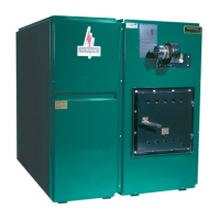
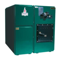
COMBINATION FURNACE INSTALLATION
Check with provincial, state or local codes concerning clearances, chimney requirements and other installation procedures
before installation. Some codes may vary from the requirements set forth in this manual.
To ensure the furnace is on a level foundation and above any possible dampness, a cement pad is recommended. It is
important that the top be level. Install as close to the chimney as possible so that a minimum of pipes and elbows may be
used.
If unit is installed in an enclosed area (furnace room), ventilation must be provided for the burner – minimum of one square inch
for every 1,000 BTU.
1. The NEWMAC COMBINATION FURNACE may be installed with the supply or return air on either side. The units leave the
factory with the return or cold air on the right when viewed looking at the oil burner end. If it simplifies the duct installation
to have the supply air on the opposite side, remove the installed panel and install it on the other side.
2. After placing the heat exchanger on the proper side of the pad, assemble the blower section to the heat exchanger section
by lining up the prepunched holes and metal screwing together.
3. Install the oil nozzle in the burner firing assembly, and check to make sure adjustments are according to Fig. 15. Install the
oil burner by mounting it on the burner mounting plate. Check to make sure the oil burner tube is aligned with the hole in
the combustion chamber.
4. Install junction box, fan/limit control, draft fan and thermostat as in Fig. 7. Note recommended setting.
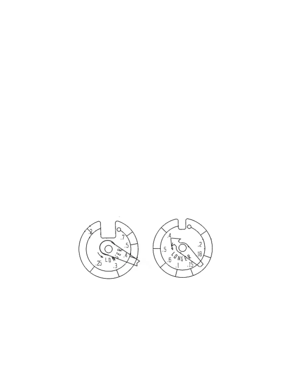
FIG. 2 - THERMOSTAT HEAT ANTICIPATORS
HONEYWELL T822 WHITE ROGERS IF30
In order to prevent short cycling, the heat anticipator in the thermostats must be set at .4 amps as indicated in the diagrams
below.
WARNING: The heat anticipator will BURN OUT IF 25 volts are applied directly to thermostat by shorting out primary control
during testing or incorrect wiring. If this happens the warranty on the thermostat is void.