4
LOW POWER
HIGH POWER
CAL ADJ
mW
mW
W
mW
µW
µW
CAL
CALPOWER
ZERO
LOW POWER
LOW POWER W/ATTN
HIGH POWER
2
200
20
■
Power Meter
■
Model 1815-C
W
W
kW
20
200
2
W
W
kW
µW
µW
mW
µW
µW
mW
µW
nW
nW
W µW
nW
nW
W
POWER
2
200
20
20
200
2
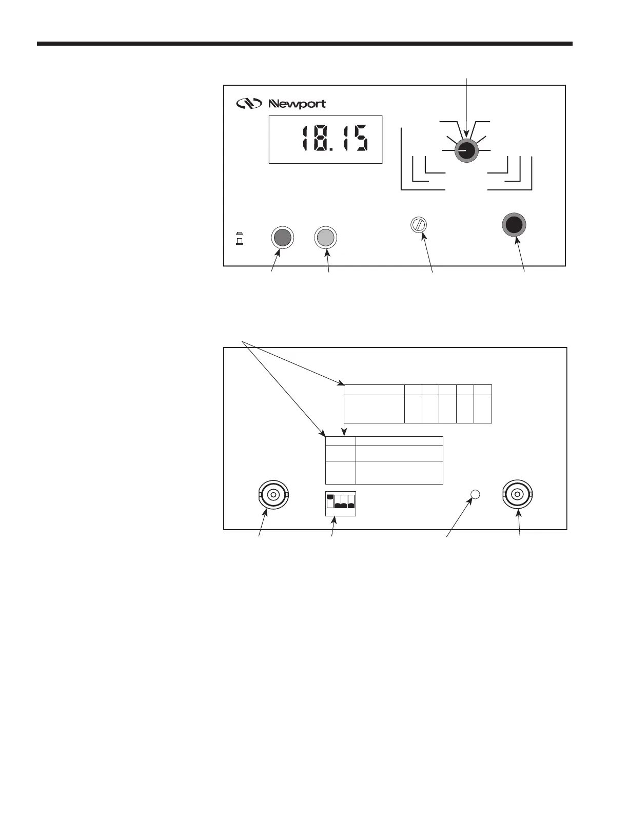
Display Calibration
Factor Mantissa
Power On/Off
Calibration Factor
Mantissa Adjust
Zero offset adjust
Range Knob
ON (1)
OFF (0)
Figure 2 — Model 1815-C Front Panel and Controls
–1 +0 +1 +2 +3
01
01
01
0 1 X 0
0 1 X 1
1 0 X 0
Low-Power (Semiconductor)
High-Power (Thermopile)
Not Accelerated
High-Power (Thermopile)
Accelerated
Adj. Reqd. See Manual
Cal. Factor Exp.
Low-Power
Low-Power w/Attn
High-Power
INPUT
1
0
ANALOG
OUTPUT
ACCEL
ADJ
DIP Switch
Input BNC Connector
Acceleration Time
Constant Adjust
Output BNC Connector
SETUP DIP Switch Bank Setting Instructions
NOTE: For Cal. Factor Exp. numbers other than shown,
see Setting the Calibration Factor Exponent in manual.
Figure 3 — Model 1815-C Rear Panel and Controls
2.2.1 Range Knob
The Range knob is shown in Figure 4. This knob adjusts the signal gain of the
Model 1815-C. The units arrayed around the knob reflect the units of measure-
ment when using a particular type of Newport detector. As an example, if a
measurement with a Low-Power detector with its attenuator was being made,
then the proper units would be read from the middle (blue) column of units
found on either side of the knob.

 Loading...


