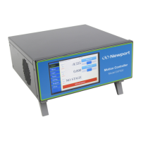
ESP302 Controller Start-Up Manual
A1270B1 - EDH0411En1021 – 02/20 32
6.0 Appendix B: General I/O Description
This chapter briefly describes all ESP302 signal types and details each of the ESP302
connector interfaces.
6.1 Digital I/O’s
All digital I/Os are TTL compatible:
• All digital I/Os are not isolated, but are referenced to electrical ground (GND).
• Input levels must be between 0 V and +5 V.
• Output levels are +5 V.
All digital I/Os are refreshed asynchronously on user requests. Therefore, digital inputs
or outputs have no refresh rate.
Typical delay is a few μs due to priorities made to other functions.
For firmware compatibility reasons, I/Os are grouped in two busses (GPIO1 and
GPIO2), each bus can be configured independently in input or output mode (default
input).
6.1.1 GPIO Connector
GPIO
NOTE
Mating connector: Male SUB-D26HD with UNC4/40 lockers.
Figure 17: GPIO connector.

 Loading...