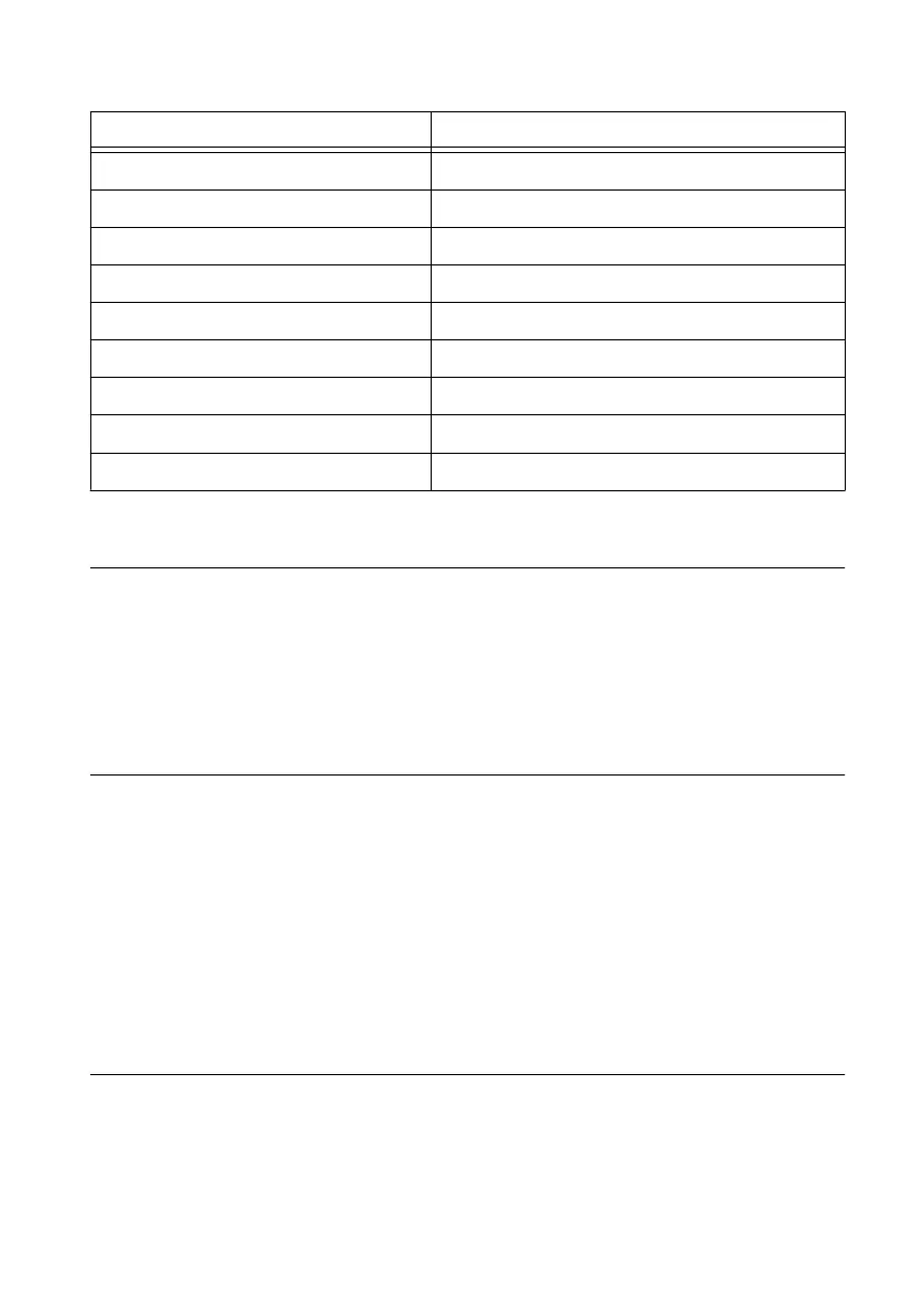
Table 1. DB-9 Pin Descriptions
Pin Signal
1 DCD
2 RXD
3 TXD
4 DTR
5 GND
6 DSR
7 RTS
8 CTS
9 RI
Using the Internal Real-Time Clock
The system clock of the cRIO-9012/9014 is synchronized with the internal high-precision real-
time clock at startup. This synchronization provides timestamp data to the controller. For
information about using the internal real-time clock to correct drift of the system clock, go to
ni.com/info and enter the Info Code crioclock. Refer to the Specifications section for the
accuracy specifications of the real-time clock.
Using the SMB Connector for Digital I/O
You can use the SMB connector of the cRIO-9012/9014 to connect digital devices to the
controller. For example, if you connect the pulse-per-second output of a GPS device to the
SMB connector of the cRIO-9012/9014, you can use the GPS device to correct for drift of the
system clock.
For software that supports GPS drift-correction and other digital I/O through the SMB
connector, go to ni.com/info and enter the Info Code criosmb.
Connecting USB Mass-Storage Devices to the
Controller
The cRIO-9012/9014 supports common USB mass-storage devices such as USB Flash drives
and USB-to-IDE adapters formatted with FAT16 and FAT32 file systems. Storage size is
limited only by the file system. The cRIO-9012/9014 does not support other types of USB
devices. You can connect USB mass-storage devices to the cRIO-9012/9014 while the
controller is operating. In order to avoid data loss or corruption, do not connect or disconnect
8 | ni.com | NI cRIO-9012/9014 User Manual and Specifications