SCC Quick Start Guide 14 ni.com
SC-2345 Carrier Considerations
The following section provides information specific to the SC-2345 carrier.
Quick Reference Label
Affix the Quick Reference Label to the inside cover of the SC-2345.
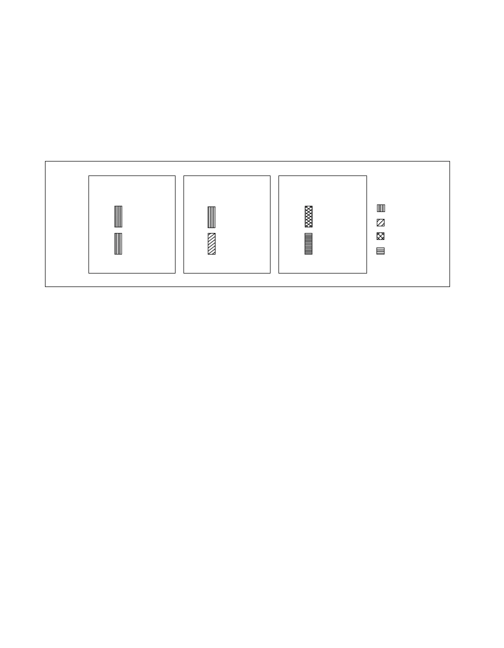
This label, shown in Figure 11, shows the possible configurations of SCC
modules. The Quick Reference Label also lists the location of each signal
on the SC-2345 carrier modules. The numbers on the label correspond to
the terminal numbers on the connector of the DAQ device.
Figure 11. SCC Module Configurations by Socket,
Function Classification, and Color Code
Blue
Green
Red
Yellow
Legend:
Dual-Stage
Analog Input
J1-8
J9-16
2nd Stage
Analog Input
Socket
1st Stage
Analog Input
Socket
Single-Stage
Analog Input
and/or Digital I/O
J1-8
J9-16
Analog Input
Single Stage
Socket (Optional)
Digital I/O
Socket (Optional)
Analog Output
and/or
GPCTR
J17-18
J19-20
Analog Output
Socket*
(Optional)
*Analog Output is not available
on AI E Series boards
General-Purpose
Counter/Timer
Socket (Optional)
 Loading...