CONNECTING THE BRINE SIDE
• The pipe connections are on the rear of the heat pump.
• Insulate all indoor brine pipes against condensation.
NOTE
Condensation may drip from the expansion
vessel. Position the vessel so that this does
not harm other equipment.
Caution
When necessary you should install venting
valves in the brine system.
• Mark the brine system with the antifreeze that is used.
• Install the supplied safety valve at the expansion ves-
sel as illustrated in the outline diagram. The entire
length of the overflow water pipe from the safety
valves must be inclined to prevent water pockets and
must also be frost-free.
• Install shut off valves as close to the heat pump as
possible so that the flow to individual cooling modules
can be shut off. Extra safety valves between the heat
pump and filterballs (according the outline diagram)
are required.
• Fit the enclosed filterballs on the incoming pipe.
• Fit the supplied non-return valves on the outgoing
pipe.
In the case of connection to an open groundwater sys-
tem, an intermediate frost-protected circuit must be
provided, because of the risk of dirt and freezing in the
evaporator. This requires an extra heat exchanger.
EXPANSION VESSEL
The brine circuit must be supplied with a pressure ex-
pansion vessel.
The brine side must be pressurised to at least 0.05 MPa
(0.5 bar).
The pressure expansion vessel should be dimensioned
as set out in the following diagram, to prevent malfunc-
tions. The diagrams cover the temperature range from
10 °C to +20 °C at pre-pressure 0.05 MPa (0.5 bar) and
the safety valve's opening pressure of 0.3 MPa (3.0
bar).
Ethanol 28% (volume percent)
In installations with ethanol (28% volume percent) as
the brine the pressure expansion vessel must be dimen-
sioned according to the following diagram.
0
0 300 600 12009000 1500
10
20
30
40
50
60
Volym tryckexpansionskärl
(l)
Totalvolym köldbärere i system
(l)
Volume pressure expansion vessel (l)
Total volume brine (l)
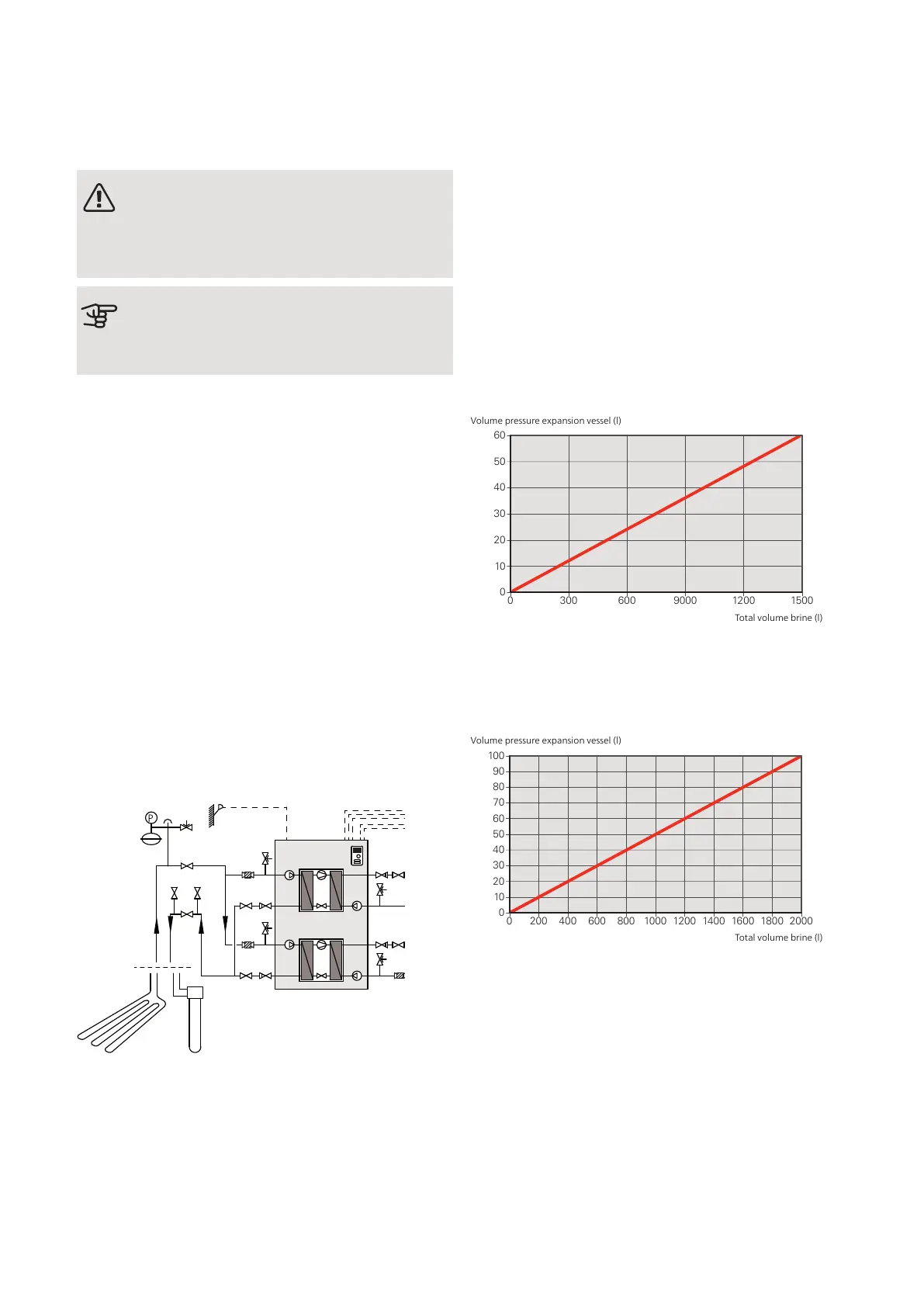
Ethylene glycol 40% (volume percent)
In installations with ethylene glycol (40% volume per-
cent) as the brine the pressure expansion vessel must
be dimensioned according to the following diagram.
0
0 200 400 600 800 1000 1200 1400 1600 1800 2000
10
20
30
40
60
70
50
80
90
100
Volym tryckexpansionskärl
(l)
Total volym köldbärare i system
(l)
Volume pressure expansion vessel (l)
Total volume brine (l)
17Chapter 4 | Pipe connectionsNIBE F1355
 Loading...


