General
All electrical equipment, except the outdoor sensors,
room sensors and the current sensors are ready connec-
ted at the factory.
• Disconnect the heat pump before insulation testing
the house wiring.
• If the building is equipped with an earth-fault breaker,
each F1355 should be equipped with a separate one.
• If a miniature circuit breaker is used this should have
at least motor characteristic “C”. See page 41 for fuse
size.
• Electrical wiring diagram for the heat pump, see page
45.
• Communication and sensor cables to external connec-
tions must not be laid close to high current cables.
• The minimum area of communication and sensor
cables to external connections must be 0.5 mm² up
to 50 m, for example EKKX or LiYY or equivalent.
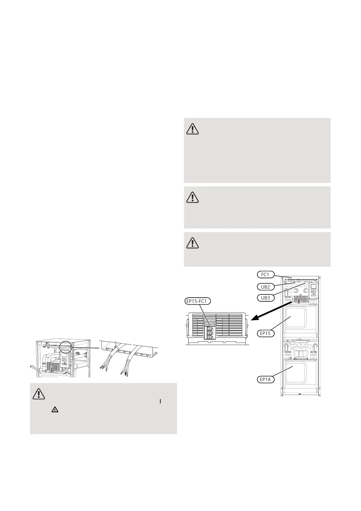
• When cable routing in F1355, cable grommets (e.g.
UB2, power cables and UB3, signal cables, marked in
image) must be used. Secure the cables in the grooves
in the panel using cable ties (see image).
NOTE
The switch (SF1) must not be moved to "" or
" " until the boiler has been filled with water.
Component parts of the product can be dam-
aged.
NOTE
Electrical installation and service must be car-
ried out under the supervision of a qualified
electrician. Cut the current with the circuit
breaker before carrying out any servicing.
Electrical installation and wiring must be carried
out in accordance with the stipulations in force.
NOTE
Check the connections, main voltage and phase
voltage before the machine is started, to pre-
vent damage to the heat pump electronics.
NOTE
Refer to the outline diagram of your system
for positioning of the temperature sensor.
EP15-FC1
FC1
UB2
UB3
EP15
EP14
MINIATURE CIRCUIT-BREAKER
The heat pump operating circuit and some of its internal
components are internally fused by a miniature circuit
breaker (FC1).
Fuse (EP15-FC1) cuts the power to the compressor if
the current is too high.
21Chapter 5 | Electrical connectionsNIBE F1355
5 Electrical connections
 Loading...


