Installation
NOTE
All electrical connections must be carried out
by an authorised electrician.
Electrical installation and wiring must be car-
ried out in accordance with the stipulations in
force.
The heat pump/indoor module must not be
powered when installing MODBUS 40.
The wiring diagram is at the end of these installation
instructions.
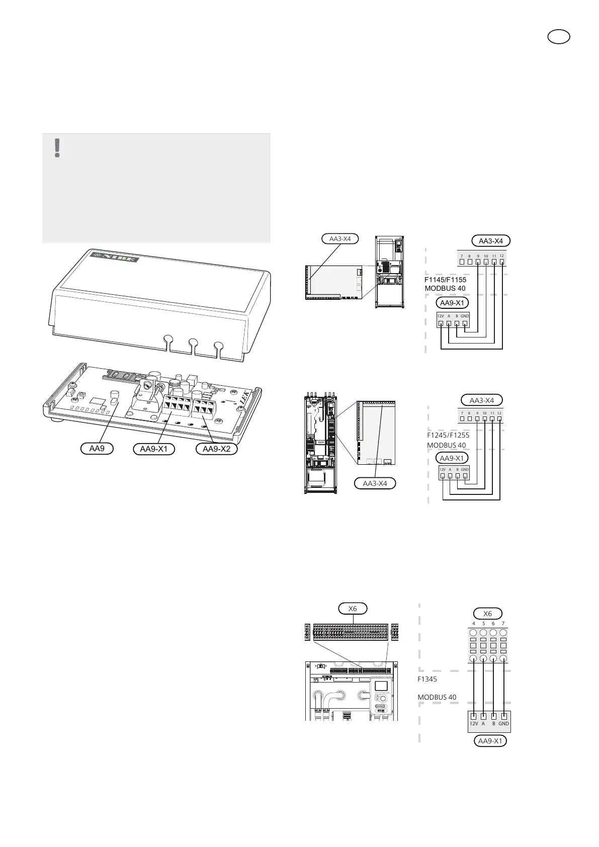
Connecting to the heat pump/indoor mod-
ule
Ground-source heat pumps
Terminal block X1 on the Modbus- card (AA9) in
MODBUS 40 is connected to X4:9-12 on the input card
(AA3) in the heat pump/indoor module.
Use cable type LiYY, EKKX or similar.
F1145/F1155
AA3-X4
MODBUS 40
F1145/F1155
AA9-X1
F1245/F1255
AA3-X4
AA9-X1
F1245/F1255
MODBUS 40
F1345
Terminal block X1 on the Modbus-card (AA9) in MOD-
BUS 40 is connected to terminal block X6:4-7 in the heat
pump.
Use cable type LiYY, EKKX or similar.
6 74 5
F1345
E
xternt
12V A B GND
13