Home
Nibe
Heat Pump
VVM 310
Service Manual
Page 28 (Setting Room Temperature)
Nibe VVM 310 - Setting Room Temperature
56 pages
Manual
Save Page as PDF
To Next Page
To Next Page
To Previous Page
To Previous Page
Loading...
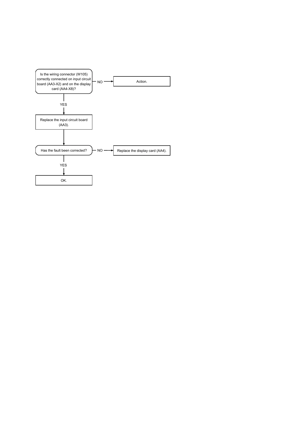
Alarm
70
-
perm.
com.error
input
card
Is
the
wiring
connector
(W105)
correctly
connected
on
input
circuit
board
(AA3-X2)
and
on
the
display
card
(AA4-X8)?
YES
YES
Has
the
fault
been
corrected?
Replace
the
input
circuit
board
(AA3).
Replace
the
display
card
(AA4).
NO
Action.
NO
OK.
NIBE™
VVM
310
Chapter
6
|
T
roubleshooting
26
27
29
Table of Contents
Main Page
Table of Contents
3
Important Information
4
Document Information
4
Safety Information
4
Indoor Module's Design
7
VVM
7
Pipe Connections
8
HVAC Components
8
Sensors Etc
8
Electrical Components
8
Miscellaneous
8
System Description Principle of Operation
9
System Diagram
10
Current Circuit Load Monitor
11
Component Description
12
Components
12
Sensors
14
Electronics
15
Troubleshooting
17
Alarm List
17
Troubleshooting Guide
25
Function Check, Components
30
Component Replacement
32
Basic
32
Main Components
35
Circuit Board and Electronics
46
Technical Data
49
Dimensions and Setting-Out Coordinates
49
Technical Specifications
50
Hot Water Capacity
51
Index
52
Other manuals for Nibe VVM 310
User Manual
72 pages
Installer Manual
76 pages
Related product manuals
Nibe VVM 500
72 pages
Nibe VVM S320
20 pages
Nibe F470
88 pages
Nibe F370
80 pages
Nibe F750
88 pages
Nibe F1245
88 pages
Nibe AMS 10-16
104 pages
Nibe F1255 Series
92 pages
Nibe F1345 Series
68 pages
Nibe F2120 Series
72 pages
Nibe F2040 Series
92 pages
Nibe F1145 series
92 pages