CBOX1050
INSTALLATION AND PROGRAMMING MANUAL
14
2
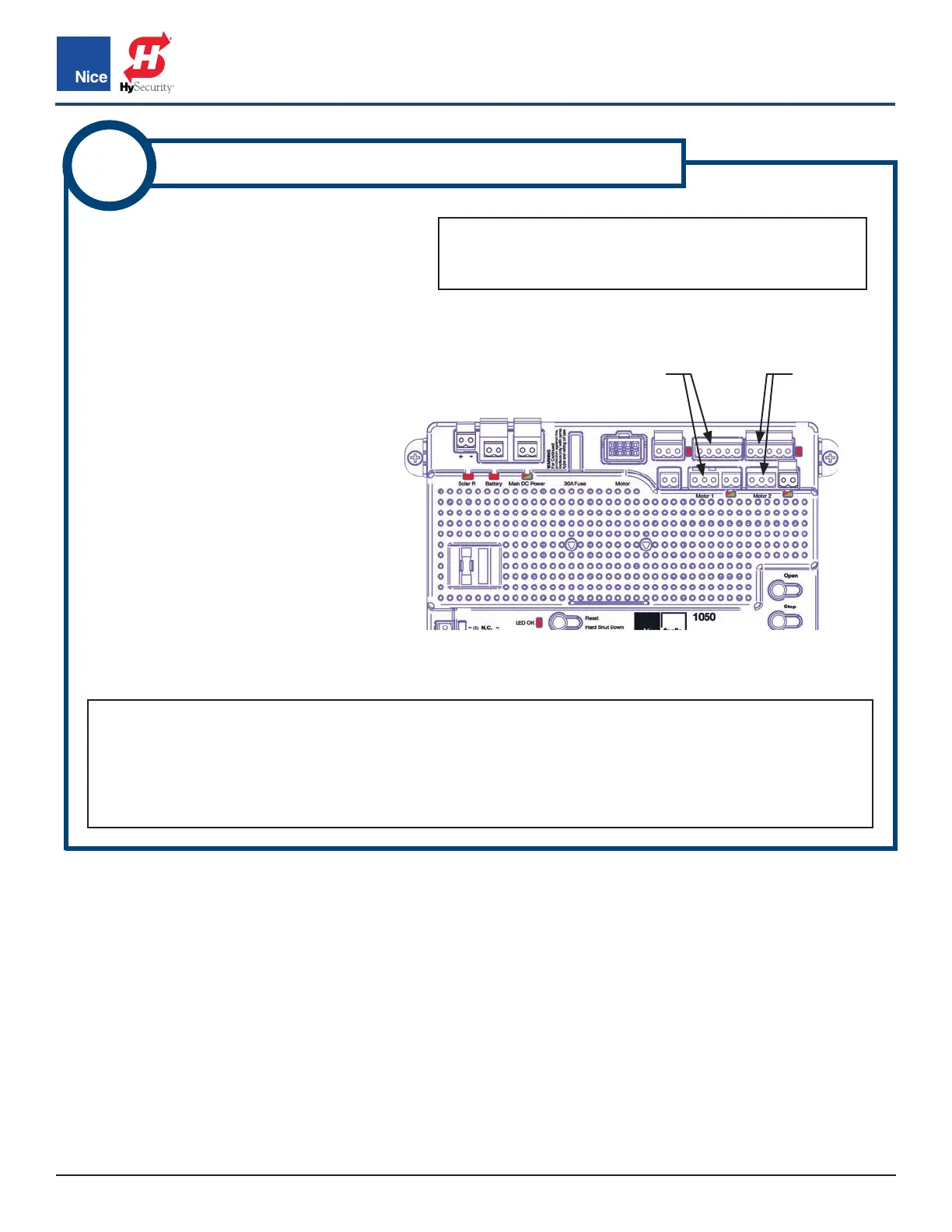
WIRE ACTUATOR(S) TO CONTROL BOARD
1. Strip actuator wires back 1/4”-5/16”
(7-8mm) and twist.
2. Remove 5-pin and 3-pin connector
from the MOTOR 1 section on control
board. If a dual gate system, also
remove both MOTOR 2 connectors.
See IMAGE 2-1.
3. Refer to wire diagram in appropriate
actuator install manual, then use
a small flat blade screwdriver to
affix wires into screw terminals of
connectors per wire diagram.
4. Plug in the wired connector to
MOTOR 1 when finished. For dual
gate systems, DO NOT connect the
MOTOR 2 connector to the control
board yet. MOTOR 2 connector will
be connected at a later step.
NOTES:
• If for a dual gate system, prepare both actuator harnesses per these instructions.
• Note that connections are different for Pull-to-Open and Push-to-Open installations.
• If a gate moves in opposite direction from what is expected, reverse the motor power lead wiring
(red & black wires) for that motor.
IMAGE 2-1: MOTOR CONNECTORS
MOTOR 1
MOTOR 2
NOTE: Refer to separate actuator installation manual
for specific instructions for wiring the actuator to the
1050 control board.
www.ApolloGateOpeners.com | (800) 878-7829 | Sales@ApolloGateOpeners.com