CBOX1050
INSTALLATION AND PROGRAMMING MANUAL
33
SECTION 8: PROGRAMMING AND CONTROLS
POWER
POWER
External Antenna
External
Receiver
for Plugin Receiver
Signal
LED, MOTOR 2
ActivationActivation
LED, MOTOR 1
LED, Solar
POLARITY
LED, Batt.
LED, Main
LED, Limits
LED, Limits
INPUTS
MOTOR 1
INPUTS
MOTOR 2
12-32
POWER
SUPPLY
VDC
12-24
VDC
BAT T.
SOLAR
PANEL
Fire Dept.
Guard
Station
Exit Probe
Alarm
Lamp
Mag.
Lock
Aux.
Out 2
Aux.
Out 1
OPEN Button
STOP Button
RESET
Button
Spare
Fuses
Incoming
30A Fuse
OK LED
CLOSE Button
UP Button
OK Button
DOWN Button
O-View Conn.
MENU Buttons
BlueBUS Conn.
OXI/A Plugin
Master/Slave
Radio Receiver
GROUND
LUG
LCD DISPLAY
Aux. In #1
Aux. In #2
Power
Accessory
Loop (Safety)
Loop (Shadow)
Entrapment
(Loop 2)
Edge Input (UL)
Shield
MOTOR 2
MOTOR 1
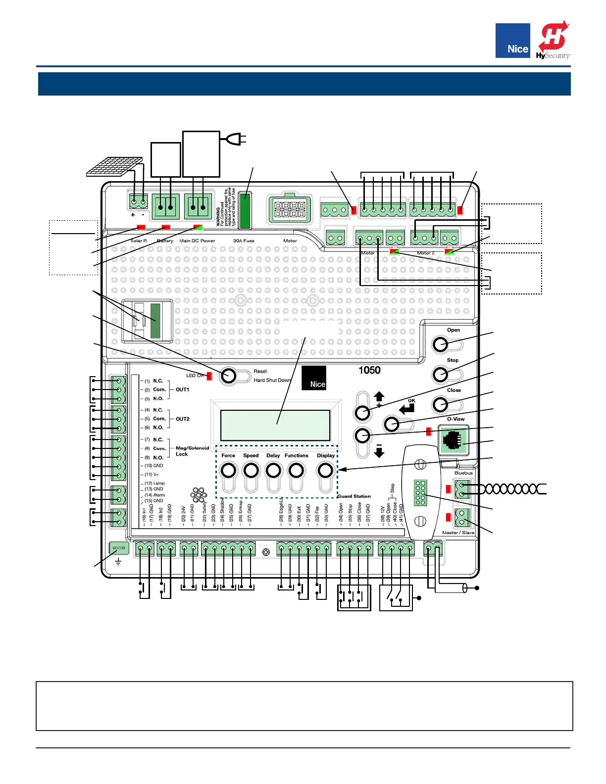
IMAGE 22-1: 1050 CONTROL BOARD COMPONENTS & CONTROLS
NOTE: Use programming buttons only after understanding the manual and its relation to the programming
sequences shown on the following pages. Care should be taken whenever changes are implemented to ensure
proper functionality and safety.
Refer to IMAGE 22-1 and TABLE 22-1 for 1050 control board option controls.
www.ApolloGateOpeners.com | (800) 878-7829 | Sales@ApolloGateOpeners.com