English – 10
English
(*) Warning! - If the post surface width is between 80 and 135 mm,
ADENQDOQNBDDCHMFVHSGHMRS@KK@SHNMSGDQD@QFD@QLNSNQjWHMFAQ@BJDS
must be turned through 90°. Then follow the instructions in ƄJ.
b),@QJSGDjWHMFONHMSRCQHKKSGDGNKDRHMSGDONRS@MCHMRDQSSGDOKTFR
then secure the gearmotor using adequate screws and washers.
Note 7KHVFUHZVDUHQRWLQFOXGHGLQWKHNLWDVWKHLUW\SHGHSHQGV
RQWKHPDWHULDODQGWKLFNQHVVRIWKHSRVWLQZKLFKWKH\DUHƄ[HG
c) - For increased stability of the gearmotor, adjust its rear feet so that
they are placed against the post. This adjustment can be made later,
VGDMSGDBNMSQNKTMHSHRQDLNUDCEQNLHSRRD@SENQSGDjQRSSHLDO@Q@-
graph 5.4).
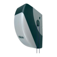
6KRUWHQLQJWKHOHQJWKRIWKHVORWWHGDUPƄJ
a) - Loosen the nut of the slotted arm, remove the stop and move the two
pins apart, checking that the distance between them is the same as
the obtained value C. Then tighten the nut, but only provisionally.
05. &KHFNLQJWKDWWKHOHQJWKRIWKHVORWWHGDUPLVVXIƄFLHQWƄJ
and 18).
a) - Move the gate leaf to the maximum leaf closing position against the
travel limit stop.
b)$WSDMCSGD@QL@MCLNUDHSTOSNV@QCRSGDKD@EOK@BHMFSGDjWHMF
bracket on the arm. Then, ƄUPO\SUHVVWKHFXUYHGDUPDJDLQVW
WKHOHDIƄJDuntil the two arms are completely extend-
ed;DSSO\IRUFHDWWKHMRLQLQJSRLQWHOERZƄWWLQJ&DXWLRQ
the arms are completely extended only when the elbow blocks
against its stop.
c) - Ensure that the gearmotor arm is level (ƄJE) and use a pencil
to mark the centre of the slots on the bracket (ƄJ), to enable
RTARDPTDMSjMD@CITRSLDMSRNEKD@EBKNRTQD
d)3GDMOQNUHRHNM@KKXjWSGDAQ@BJDSNMSGDKD@EVHSG@BK@LONQ@CGDRHUD
tape and move the leaf to the maximum opening position, against the
kNNQLNTMSDCSQ@UDKRSNO
e) - With the leaf in this position, check the gate as shown in ƄJ:
stretch a piece of string passing exactly above the two pins of
the slotted arm through to the leaf hinge pin. If the string is found
between the hinge pin and post in the area of the hinge pin (posi-
tion “BB” in ƄJ), extend the slotted arm by a few millimetres
(value “C”) and repeat the check. Repeat the procedure several times
HEMDBDRR@QXTMSHKSGDRSQHMFHRKNB@SDCADSVDDMSGDF@SDSQ@MRHSYNMD
and the leaf hinge pin (position “AA” in ƄJ), and until the arm no
KNMFDQBNLDRHMSNBNMS@BSVHSGSGDjWDCNARS@BKDADGHMCSGDONRS
06. &XWWLQJWKHVORWWHGDUPƄJ
After ensuring correct operation of the entire arm, cut the excessive
part of the slotted arm as described below.
a) 3Q@BD@KHMDNMSGDRKNSSDC@QLHMSGDDW@BSONRHSHNMRODBHjDCHMOG@RD
1 in ƄJ Then remove the arm from the bracket and cut the
excess section of the arm.
b) - After removing any burrs found after cutting, re-assemble the arm
components with reference to ƄJ.
07. )L[LQJWKHDUPRQWKHOHDIƄJ
a) - Drill the leaf at the marked points; remove the bracket from the arm
@MCjWHSSNSGDF@SDKD@EVHSG@CDPT@SDRBQDVRNote 7KHVFUHZV
DUHQRWLQFOXGHGLQWKHNLWDVWKHLUW\SHGHSHQGVRQWKHPDWHULDODQG
WKLFNQHVVRIWKHSRVWLQZKLFKWKH\DUHƄ[HG
b)%HWSGD@QLSNSGDAQ@BJDSHMRDQSHMFSGDOHM@MCRSNOADMYHMFImpor-
tant - Check that the bracket and arm are perfectly level. If neces-
sary, loosen the bracket screws and level as required.
c) /DQL@MDMSKX@MBGNQSGDSQ@UDKRSNORSNSGDkNNQ in the same position
as established at the beginning of paragraph 3.4.
08. Checking perfect leaf closure.
a) - Close the leaf completely and ensure that it is placed against the trav-
el stop; then shake by hand to check and ensure that the gearmo-
SNQQDL@HMRjQLKXHMONRHSHNM(ESGHRHRMNSRNOQNBDDC@RCDRBQHADC
below; otherwise skip to phase 09:
1.QDLNUDSGDRKNSSDC@QLEQNLSGDjWHMFAQ@BJDSNMSGDKD@E
2. loosen the bracket screws and move it by a few millimetres in the
direction of the gearmotor;
A
0
50 100 150 200 250
B
C
300
250
200
150
10 0
50
80
100
120
140
160
180
200
220
240
260
mm
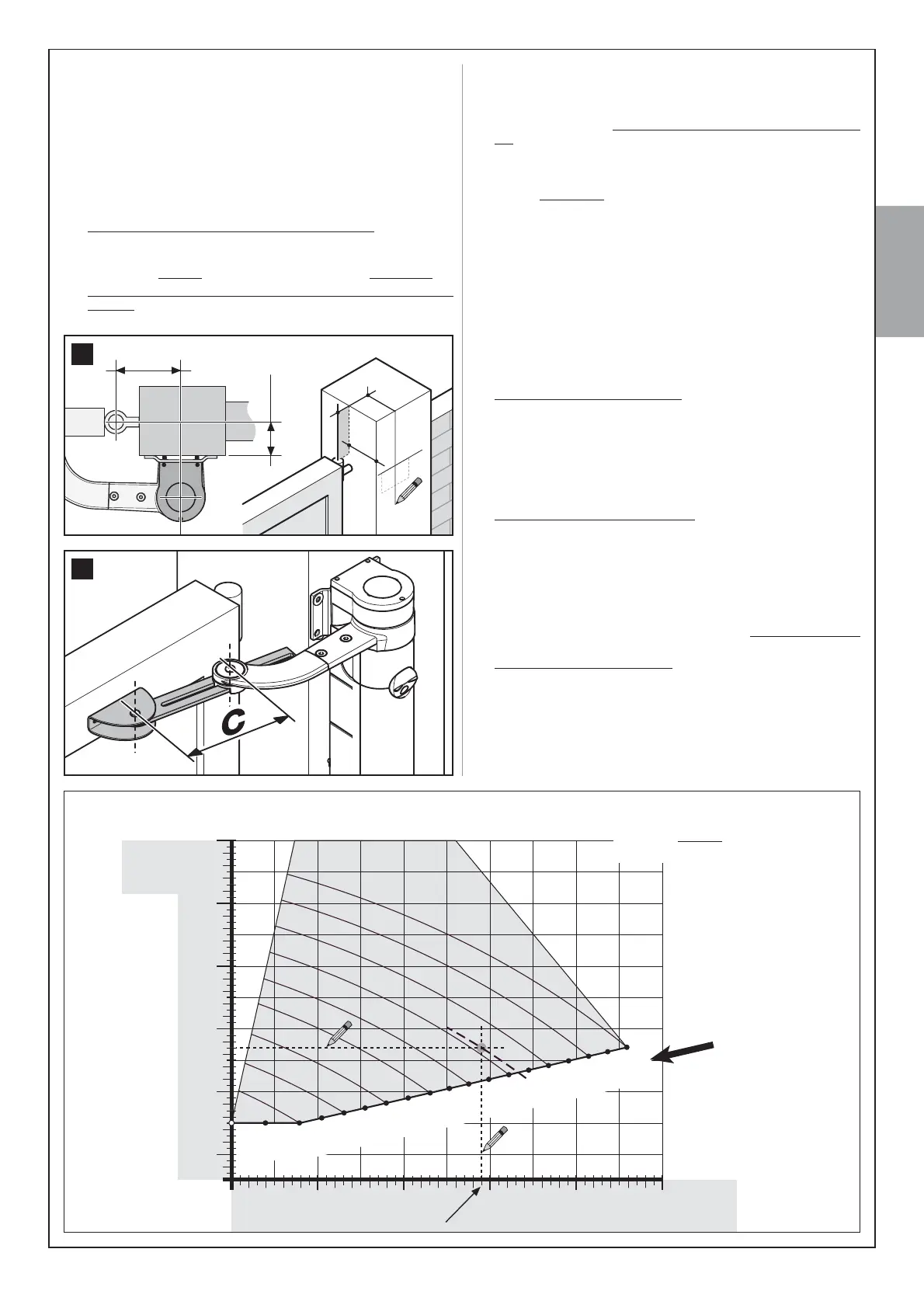
B = 145
*5$3+(see paragraph 4.1B)
EXAMPLE: if value B on the gate post
is measured at mm and value A is
135 mm value C will be 210 mm
1
A
B
A
B
11
 Loading...