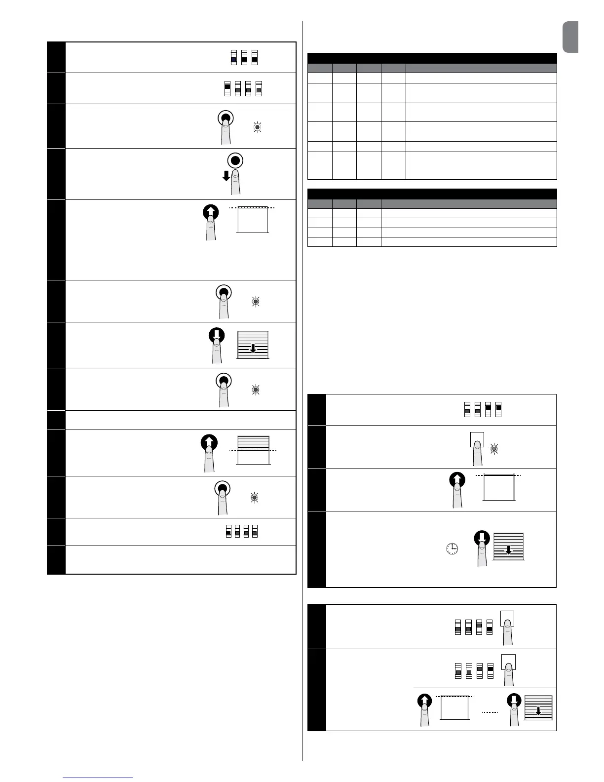
03. Keep the STOP button pressed
until the led is on with xed red
light (after about 3 seconds)
3”
04. Release the STOP button
05. Press the OPEN button to bring
the door to the desired open po-
sition
Caution!
- if the sense of rotation does not match the set direction (OPEN button =
opening direction, it is necessary to swap the positive and negative poles
of the motor cables and repeat the learning procedures from the start
06. Keep the STOP button pressed
for 3 seconds until the led ashes
once with red light
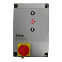
13. Set dip switches A-3 and A-4 as per Table 3 for the desired operating
mode and conrm the setting of the dip switch with the P1 button on
the control unit
CAUTION! – The recognition phases must not be interrupted. If there is
an interruption, you must repeat the entire recognition process.
Once the position learning phase has been completed, it is necessary
to carry out learning about the handling forces: carry out 4 complete
manoeuvres; if the manoeuvre is not completed (e.g. for amp meter
intervention or stop or photo intervention) it is not counted. Until this
phase is complete, the OK led is ashing with red and green light during
the manoeuvre, THAT IS CARRIED OUT AT MAXIMUM FORCE.
Note: if the speed or slow down positions are modied or if the
sensitivity is activated, the force learning phase must be repeated.
4.5 - Operating modes
CAUTION! - If the functions of Table 3 are programmed with the Oview
programming unit, it is necessary to set the dip switches to OFF.
TABLE 3: DIP SWITCH A
DIP1 DIP2 DIP3 DIP4 Function
OFF OFF OFF OFF
Hold-to-run movement
ON X OFF OFF
Acquisition of positions and status of the ALT
input
OFF ON OFF OFF
Rotation direction of the encoder reversed
(only for absolute encoder)
OFF X OFF ON
Industrial mode (semi-automatic opening –
hold-to-run closing), if positions recognised
OFF X ON OFF
Semi-automatic mode, if positions recognised
OFF X ON ON
Automatic mode with adjustable pause time,
if positions recognised (see para. 4.5.1 “Set-
ting the automatic closing pause time”)
TABLE 4: DIP SWITCH B
DIP1 DIP2 DIP3 Function
OFF X Sensitivity disabled
ON X Sensitivity enabled*
X X OFF Motor with encoder
X X ON Motor with electromechanical limit switch
* Note: the sensitivity parameter allows reducing the door strength of interven-
tion against an obstacle considerably.
During the “Learning about the safety devices” procedure, the control
unit stores the status of dip switches A and B. At the end of this proce-
dure, a variation in the dip switches causes the OK led to ash quickly
with red and green light alternately to highlight the change in congura-
tion; in this phase the control unit allows no commands to be executed.
It is necessary to carry out a new “Learning about the safety devices”
procedure (paragraph 4.3) or press the P1 button for 2 seconds.
Once the positions have been acquired, it is necessary to perform 4
complete manoeuvres to get the control unit to store the force required
to move the door; the manoeuvres are represented by the OK led ash-
ing slowly with red and green light alternately.
The “force and sensitivity” parameters can be adjusted with the Oview pro-
grammer (accessory).
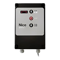
4.5.1 - Setting the automatic closing pause time
01. Set dip switches A-3
and A-4 to ON
ON
OFF
1 2 3 4