English
13
Remember that the unit is live (electrocution hazard, risk of fire ...) and contains electronic components that, due to their
nature, are particularly fragile.
Make sure you have all the necessary materials available and that they are suitable for this use.
2.1) INST
ALLATION: Read all the instructions through at least once!
Before actually starting, carefully analyse all the risks relating to the automation you are about to install. Verify the sturdiness and
mechanical consistency of the gate, observe the safety margins and minimum distances. Evaluate with particular care the safety
devices to be installed and where to install them, always install an emergency stop device, in other words, a category 0 stop
device (compulsory interruption of power to the actuators).
Once you have carefully analysed the risks involved, you can install the unit, the actuators, the control (key selector or push
button panel) and safety (emergency stop, photoelectric cells, sensitive edges and flashing light) devices for the automation.
When installing the actuators, scrupulously follow all the instructions given in the instruction manuals which must be enclosed
with the motors. If some points are not very clear, do not install the unit without first having cleared up all doubts by consulting
our TECHNICAL OFFICE.
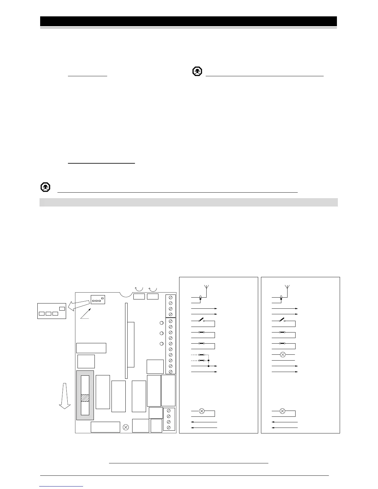
2.2) CONNECTIONS DIAGRAM:
Only when the gearmotor and relative control and safety elements have been installed can you do the wiring, following the
instructions given below.
While you are connecting the unit it must not, under any circumstances, be electrically powered
.
As mentioned previously, some connections are different for the OTA 30 and ROA 30 versions
Switch 1 ON = Automatic movement
Switch 2 ON = Condominium functioning mode
Switch 3 ON = Remote reversal with photocell command
Switch 4 ON = Courtesy light on flashing light output
& To safeguard the operator and avoid damaging components while you are wiring:
the unit must, under no circumstances, be electrically powered.
•
•
MIN
MAX
1
2
3
4
PROGRAMMABLE
FUNCTIONS
FUSE 500mA
FUSE 5A
SECONDARY
TRANSFORM
T. L. T. P.
STEP-BY-STEP
PHOTOCELL
STOP
MOTOR
AP-CH
STOKE
END
CH-AP
CAP
INRUSH
RELAY
COMMON
RELAY
CLOSE
RELAYCOR
OPEN
RELAY
PRIMARY
TRANSFORM.
RADIO
++
44
43
42
41
14
13
12
11
10
9
8
7
6
5
4
3
2
1
+
–
FCC
FCA
(OPTIONAL)
STOP
PHOTOCELL
STEP-BY-STEP
2° RADIO CH
ANTENNA
24 Vcc
Max 100 mA
OTTO
LUCY 230 Vac
MAX 100 W
"L" 230 Vac
"N' 50 Hz
44
43
42
41
14
13
12
11
10
9
8
7
6
5
4
3
2
1
GATE OPEN INDICATOR
24 V Max 3 W
STOP
PHOTOCELL
STEP-BY-STEP
2° RADIO CH
ANTENNA
24 Vac
Max 100 mA
ROBO
LUCY 230 Vac
MAX 100 W
"L" 230 Vac
"N' 50 Hz
Fig. 2
 Loading...