4
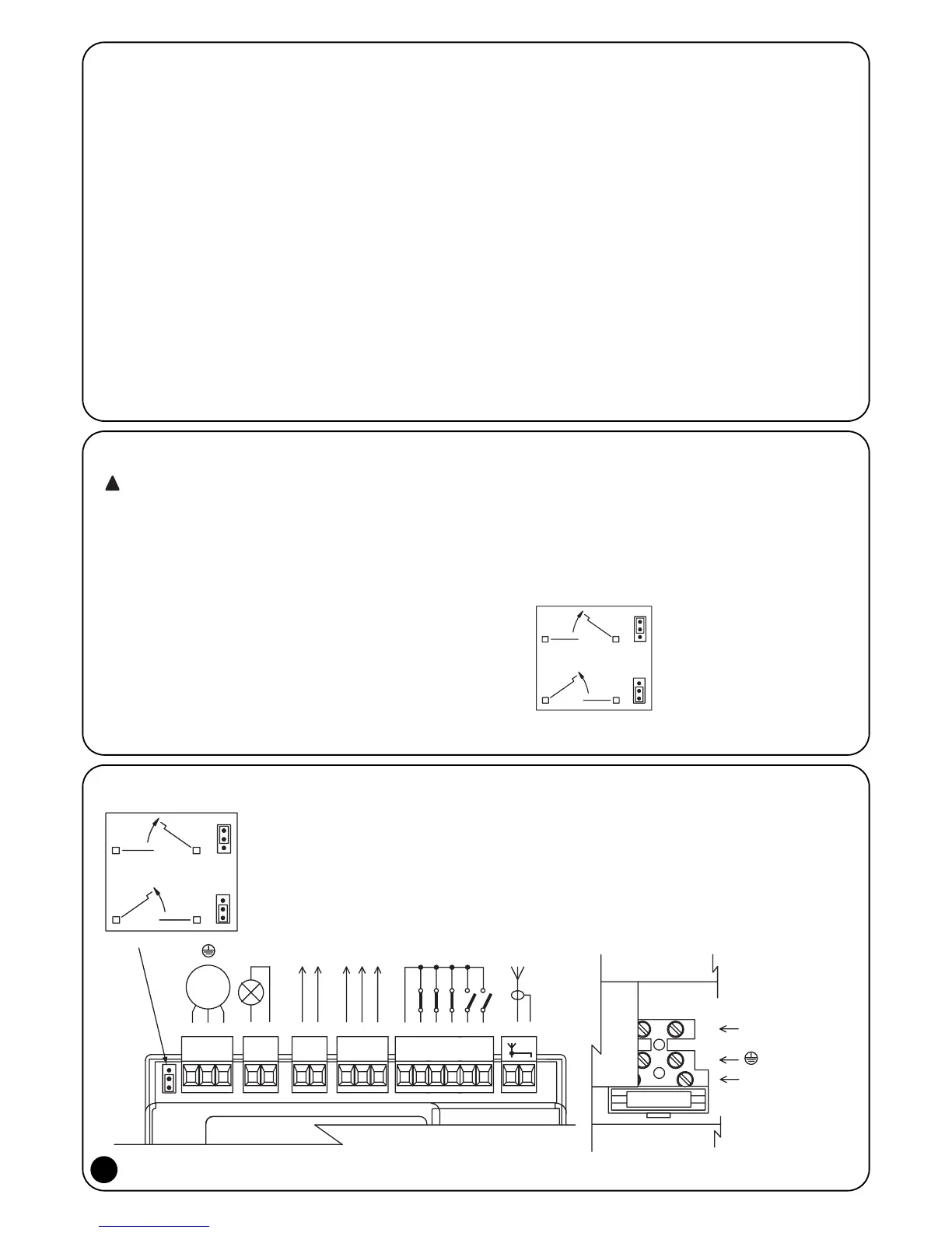
2.3.1) Electrical diagram
2.2) Preliminary checks
Before starting any kind of work, ensure that all the material is suit-
able for installation and complies with legal requirements. As well as
checking all the points listed in the “Warnings for fitters” file, this sec-
tion also contains a specific check list for the POA1 control unit.
• The “mechanical stops” must both be able to stop the gate from
moving and easily absorb all the kinetic energy accumulated dur-
ing movement (if necessary, use the stops for POP motors).
• The power supply line must be protected by magneto-thermal and
differential switches and equipped with a disconnection device.
There must be over 3mm between the contacts.
• Power the control unit using a 3 x 1.5mm
2
cable. Install an earth
plate near the control unit if the distance between the control unit
and the earth connection is over 30m.
• Use wires with a minimum cross section of 0.25mm
2
to connect
extra-low voltage safety circuits.
• Use shielded wire if the length is over 30m and only connect the
earth braid on the control unit side. The cross-section of the con-
nection cable for the motor must be at least 1.5mm
2
.
• Do not connect cables in buried boxes even if they are complete-
ly watertight.
2.3) Electrical connections
Unplug the unit from all sources of electricity in order
to ensure the fitter is protected and to prevent compo-
nents being damaged during electrical or radio receiver
connection.
• With the exception of the photocell inputs when the PHOTOTEST
function is activated, if the inputs of the NC (Normally Closed) con-
tacts are not in use they should be jumped with the “COMMON”
terminal. Refer to paragraph 2.3.6 for further information.
• If there is more than one NC contact on the same input, they must
be connected in SERIES.
• If the inputs of the NO (Normally Open) contacts are not used they
should be left free.
• If there is more than one NO contact on the same input, they must
be connected in PARALLEL.
• The contacts must be mechanical and potential-free. Stage con-
nections, such as those defined as "PNP", "NPN", "Open Collec-
tor", etc. are not allowed.
• If the leafs overlap, use jumper E (Figure 1) to select which motor
starts up first during opening. M1 has an incorporated control unit,
M2 does not.