8
2.3.7) Checking the connections
WARNING: The next operations involve work being car-
ried out on live circuits. Some parts have mains voltage
running through them and are therefore EXTREMELY DAN-
GEROUS! Pay maximum attention to what you are doing
and NEVER WORK ALONE!
The system can be checked once the connections for the automa-
tion have been made.
1. Power the control unit and check that all the LEDs flash rapidly for
a few seconds.
2. Check that there is a voltage of approximately 32Vdc on terminals
9-10. If not, unplug the unit immediately and carefully check the
connections and input voltage.
3. After initially flashing rapidly, the P1 LED will indicate the control
unit is working correctly by flashing regularly at 1 second intervals.
When there is a variation in the inputs, the “P1” led will rapidly flash
twice to show that the input has been recognised.
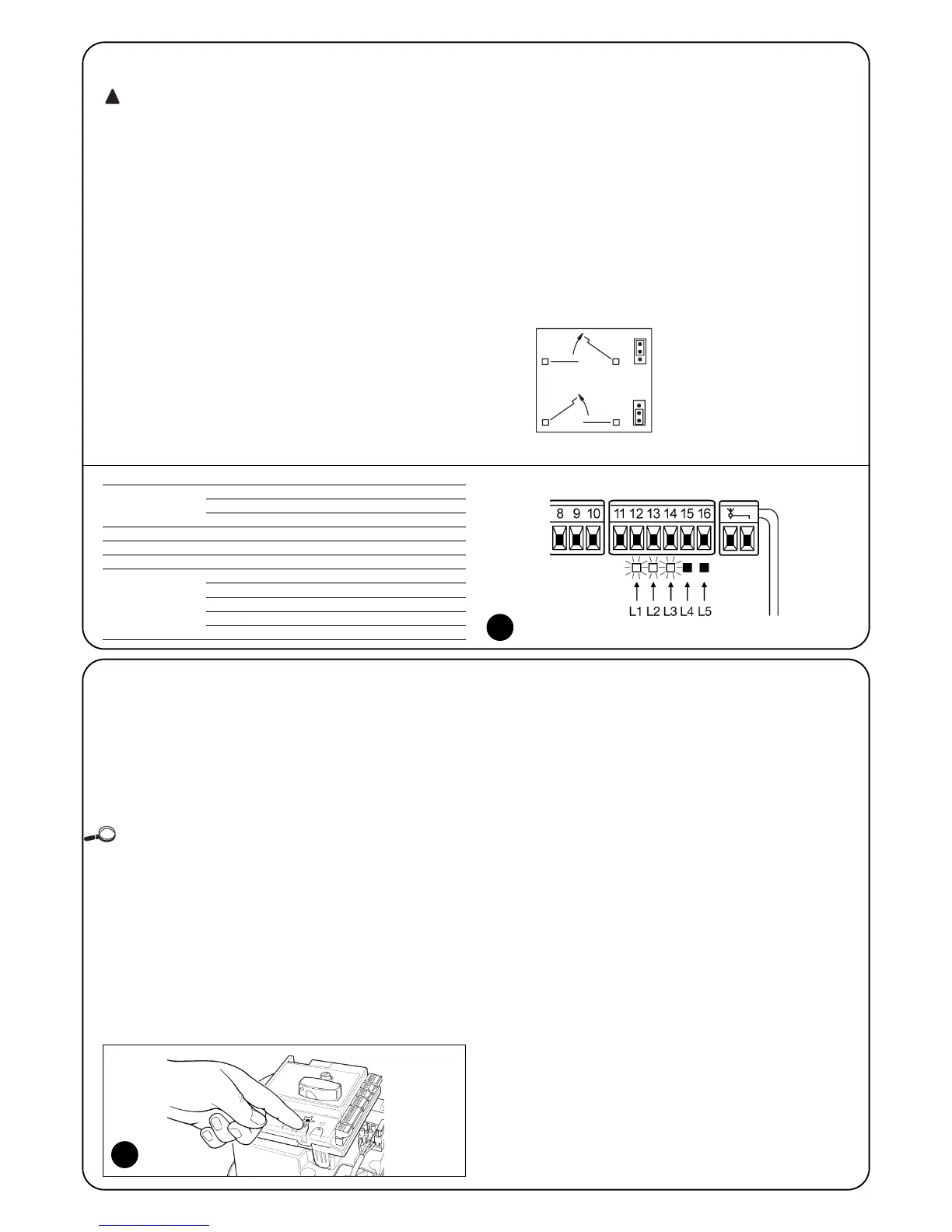
4. If the connections are correct, the LED for the “NC”-type inputs
will be on, while those for the “NO” type inputs must be off. Here
follows Figure 8 illustrating the LEDs on, and the summary table of
the various possible situations:
5. Check that the relative LEDs switch on and off when the devices
connected to the inputs are operated.
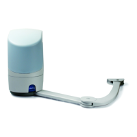
6. Check that by pressing P2 both motors perform a short opening
manoeuvre, and the motor of the upper leaf starts first. Block the
manoeuvre by pressing P2 again. If the motors do not start up for
opening, invert the polarities of the motor cables. If, however, the
first one to move is not the upper leaf, operate jumper E (see fig-
ure).
INPUT INPUT TYPE STATUS LED
STOP STOP NC L1 On
CONSTANT RESISTANCE L1 On
STOP 8,2KΩ
PHOTO L2 On
PHOTO 1 L3 On
STEP-BY-STEP L4 Off
AUX OPEN PARTIALLY type 1 L5 Off
OPEN PARTIALLY type 2 L5 Off
OPEN ONLY L5 Off
CLOSE ONLY L5 Off
PHOTO2 L5 On
2.4) Automatic search system for the limit switches
On the successful completion of the various controls, start the auto-
matic search system phase for the limit switches. This work is nec-
essary as the POA1 control unit must “measure” how long the open-
ing and closing manoeuvres take.
This procedure is completely automatic and detects the mechanical
opening and closing stops by measuring the load on the motors.
If this procedure has already been carried out, in order to reactivate it, the
user must first delete the memory (see the “Memory deletion” chapter). In order
to check whether the memory contains any limit switch parameters, turn the
power supply to the control unit on and then off again. If all the LEDs flash rapid-
ly for approximately 6 seconds, the memory is empty. If, however, they only flash
for 3 seconds, the memory already contains some limit switch parameters.
• Before starting limit switch searching, make sure that all the safety
devices are enabled (STOP, PHOTO and PHOTO1).
The procedure will be immediately interrupted if a safety device trig-
gers or a command arrives.
• Ideally the doors should be half open, although they can be in any
position.
• Press the P2 button to begin searching, which runs as
follows:
- Both motors open briefly
- Motor closes the lower leaf until it reaches the mechanical closing
stop.
- The upper leaf motor closes until it reaches the mechanical clos-
ing stop.
- The motor of the upper leaf begins to open.
- After the programmed delay, opening of the lower leaf begins.
If the delay is insufficient, block the search by pressing P1, then
modify the time (see the “Programming” chapter).
- The control unit measures the movement required for the motors
to reach the opening mechanical stops.
- Complete closing manoeuvre. The motors can start at different
times, the aim is to prevent the leafs from shearing by maintaining
a suitable delay.
- End of the procedure with memorisation of all measurements.
All these phases must take place one after the other without any
interference from the operator. If the procedure does not continue
correctly, it must be interrupted with the P1 button.
Repeat the procedure, modifying some parameters if necessary, for
example the current sensitivity cut-in thresholds (see the “Program-
ming” chapter).
8
9