12 Commander C200/C300 Step By Step Guide
Issue Number: 2
The drive must be connected to the system ground of the AC supply. The ground wiring must
conform to local regulations and codes of practice.
Table 6-2 Protective ground cable ratings
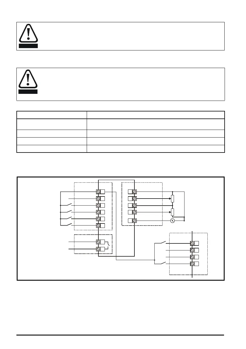
Control connections
The control terminals are configured by default for the arrangement shown below:
Figure 6-5 Commander C200/C300 control terminal connections
* 250 Vac maximum (UL class1)
** Commander C300 uses ‘Safe Torque Off’ so terminal 11 is unassigned on the Commander C300. When using a
Commander C300 refer to the 'Safe Torque Off' wiring instructions above.
After completing step 6 re-fit the terminal cover (refer to step 5).
Electrochemical corrosion of grounding terminals
Ensure that grounding terminals are protected against corrosion i.e. as could be caused
by condensation.
The ground loop impedance must conform to the requirements of local safety regulations.
The drive must be grounded by a connection capable of carrying the prospective fault
current until the protective device (fuse, etc.) disconnects the AC supply.
The ground connections must be inspected and tested at appropriate intervals.
Input phase conductor size Minimum ground conductor size
≤ 10 mm²
Either 10 mm² or two conductors of the same cross-sectional area as the
input phase conductor
> 10 mm² and ≤ 16 mm²
The same cross-sectional area as the input phase conductor
> 16 mm² and ≤ 35 mm² 16 mm²
> 35 mm²
Half of the cross-sectional area of the input phase conductor
9
10
11
12
13
14
41
42
1
2
7
4
5
31
32
35
36
24 V user
Zero frequency
Drive enable**
Run forward
Run reverse
Analog input 1/
Analog input 2 select
10 kΩ
10 kΩ
Frequency
reference 1
Frequency
reference 2
Frequency output
Digital I/O
24 V user
Digital I/O1
Digital Input 2
Digital input 3
Digital input 4
Digital input 5
Analog I/O
0V
Analog input 1
10 V user
Analog input 2
Analog output 1
Drive ok
Relay 1*
Safe Torque
Off
ST01
0V
STO1
0VSTO2
ST02
** C300 only
 Loading...