8 Commander C200/C300 Step By Step Guide
Issue Number: 2
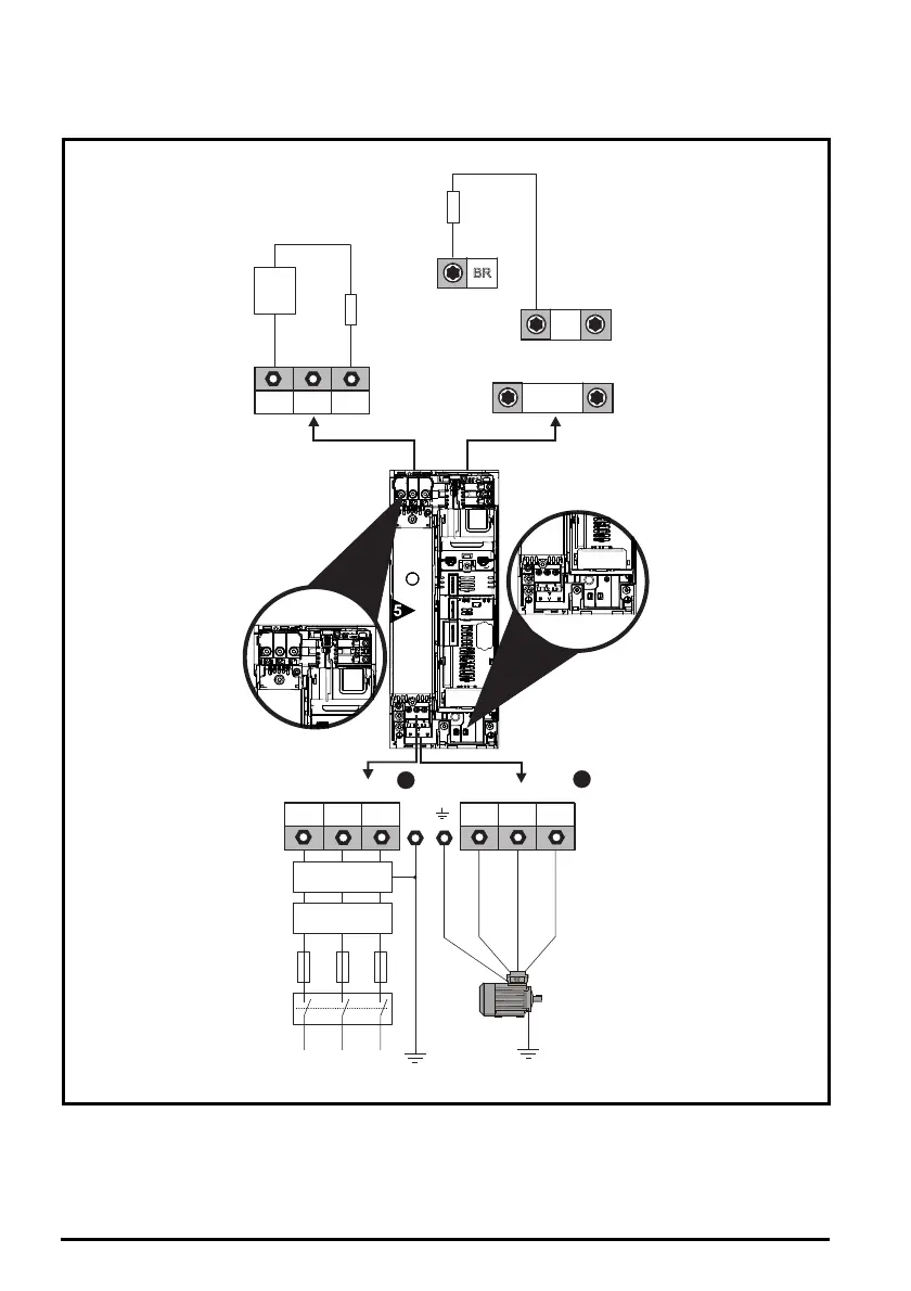
Power and Ground connections
Connect the supply and motor connections using the cables and fuses quoted in the table shown in Step 4.
Figure 6-1 Size 5 power and ground connections
The upper terminal block (1) is used for AC supply connection.
The lower terminal block (2) is used for Motor connection.
On size 5, the supply and motor ground connections are made using the M5 studs located near the
plug-in power connector. Refer to Figure 6-1.
Optional heatsink
mounted brake
resistor (M600
and above)
BR
+DC
-DC
DC / Brake connections
BR
Optional external
braking resistor
Thermal
overload
protection
device
DC -
DC +
L1 L2
L2L1 L3 U V W
Optional EMC
filter
Optional
line reactor
Fuses
L3
Mains
Supply
Motor
Optional ground
connection
Supply
Ground
PE
AC Connections Motor Connections
1
2
 Loading...