Safety information Introduction Product information System configuration
Mechanical
Installation
Electrical Installation
58 Unidrive M Modular Installation Guide
Issue Number: 2
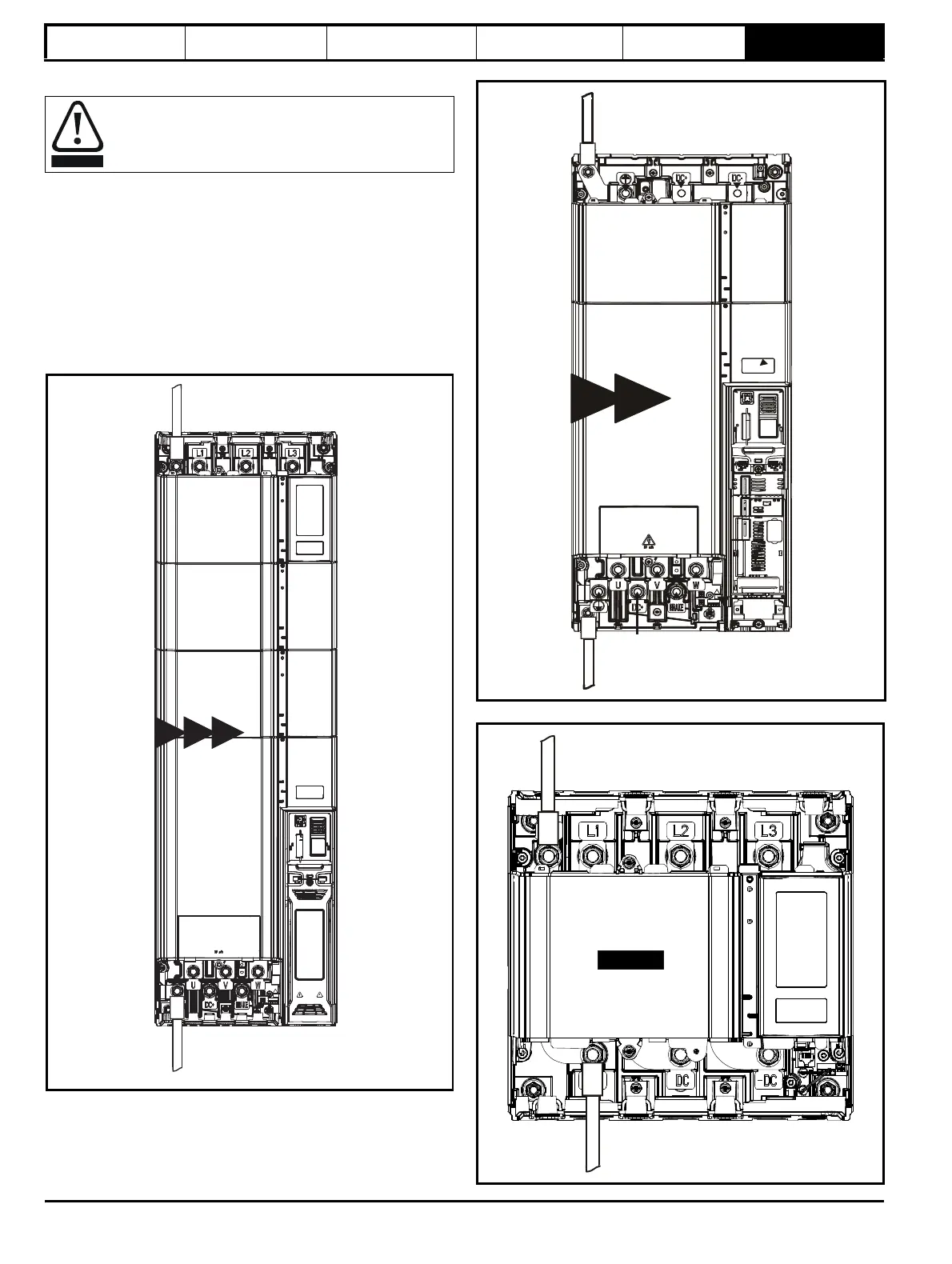
6.1.3 Ground connections
On a Unidrive M size 9, 10 and Rectifier, the supply and motor ground
connections are made using an M10 bolt at the top (supply) and bottom
(motor) of the drive. See Figure 6-5 Unidrive M size 9E/10E/9A ground
connections on page 58.
The supply ground and motor ground connections to the drive are
connected internally by a copper conductor with a cross-sectional area
given below:
9E/10E: 75 mm
2
9A/9D/10D: 120 mm
2
Rectifier: 128 mm
2
Figure 6-5 Unidrive M size 9E/10E/9A ground connections
Figure 6-6 Unidrive M size 9D/10D ground connections
Figure 6-7 Unidrive M rectifier ground connections
Electrochemical corrosion of earthing terminals
Ensure that grounding terminals are protected against
corrosion i.e. as could be caused by condensation.
Motor
ground
Supply
ground
9E 10E
9A
Motor
ground
Supply
ground
Rectifier
+