Safety information Introduction Product information System configuration
Mechanical
Installation
Electrical Installation
72 Unidrive M Modular Installation Guide
Issue Number: 2
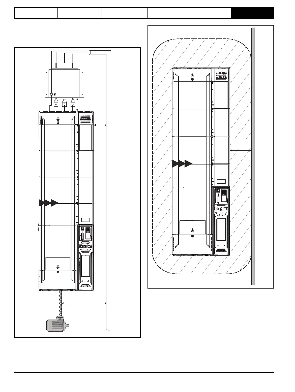
6.10.4 Compliance with generic emission standards
Use the recommended filter and shielded motor cable. Observe the
layout rules given in Figure 6-18. Ensure the AC supply and ground
cables are at least 100 mm from the power module and motor cable.
Figure 6-18 Supply and ground cable clearance
Avoid placing sensitive signal circuits in a zone 300 mm (12 in) all
around the power module.
Figure 6-19 Sensitive signal circuit clearance
³100mm (4in)
³100mm
(4in)
³100mm (4in)
Master
9E 10E 9A
³300mm
(12in)
Sensitive
signal
cable
Master
9E 10E 9A