8
●12.
About Mode
13.
When You Select Mode 1 (Digital Tachometer Mode) for Measurement
DT-501X/DT-501F have ve modes (functions) which can be selected according to the measurement purpose.
* The mode 1 (digital tachometer mode) is set in the factory setting.
For the lists of parameters and functions to be set in each mode, refer to pages 20 and 21.
• When you select mode 1 (digital tachometer mode) for measurement (The digital tachometer mode is set in the factory setting.)
•
Parameter setting items in mode 1 (digital tachometer mode) nd numerical values to be set according to the above example
Mode
No.
Mode description Details
Page No.
for the setting method
1 Digital Tachometer Mode* Digital tachometer / used as speedmeter●Displays the proportional value to the input p.8 - 9
2 Elapsed Timecounter Mode Used as the elapsed time display in a certain period●Displays the inversely proportional value to the input p.10 - 11
3 Time Width Meter Mode Measures time for the period when the signal is ON (or OFF) and displays it p.12 - 13
4 Flowmeter Mode Displays the instantaneous ow amount p.14 - 15
99 Test Mode Executes the self diagnosis p.19
Setting Method
● Setting example (for measuring the peripheral speed of the roller)
● Setting method
(1) Mode
(2) Parameter
As in the gure on the left, the rotary encoder is connected to the feed
roller via coupling in the paper manufacturing process. To display the
peripheral speed (m/min.) of the feed roller in DT-501under the following
conditions:
[Conditions]
● Servo motor (pulse input)
● Diameter of the feed roller
● Peripheral speed of the roller diameter of 90mm ●
●0.09m×3.14)×500rpm ● 141.3m/min
●●●●
*Suppose that the revolution speed
in the detection section is 500rpm
because the revolution speed is not
instructed.
Circumference
of the roller
Revolution
speed*
Normal display
Mode setting
Finish setting
The main display shows “0”.
0
0
- 0 1 -
Press the SET key.
The display goes to mode 1 (digital tachometer
mode).
The numerical value does not
need to be changed and you can
proceed to the next step.
* Every time you press the
s
key,
the mode No. switches.
Press and hold the SHIFT + MODE keys
for 5 seconds or more.
The main display shows the current set
mode No. after blinking.
* When you are setting for the rst time after the
purchase of this unit, mode 1(digital tachometer
mode) in the factory default setting is displayed.
Note) If you change the mode settings, each parameter and function setting value will return to the factory default setting value.
* For the description about the parameter functions, refer to page 20.
No. Setting item Setting range
Default setting value
Numerical value to be set according to the above example
Display Description
P1
Pulse count per revolution
1 - 9999p/r _ _ 0001 1p/r 600p/r Enter the pulse count of the rotary encoder.
P2
Revolution speed in the
detection section
1 - 99999rpm _01000 1000rpm 500rpm Enter some numerical value as the revolution speed is not instructed.
P3
Value to be displayed
(with decimal point)
0.00001 - 999999 001000 1000 141.3 Refer to the above "Setting example".
P4 Display cycle
0.2/0.5/1.0/2.0/
5.0/10/15/30/60 sec.
_ 1.0 _ 1 sec. 1 sec. Measure using the default setting value as no special instruction is provided.
P5 Auto zero time 0.1 - 150 sec. _ _ 006.0 6.0 sec. 6 sec. Measure using the default setting value as no special instruction is provided.
P6 Input lter 10/30/100/0.02kHz _ 10_ 10kHz 30kHz As the rotary encoder is used as a sensor, select "30".
Set each setting item for mode and parameter according to the following procedures.
(For the setting method of functions, refer to pages 16 and 17.)
Digital tachometer mode
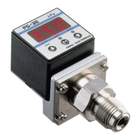
www.calcert.com sales@calcert.com1.888.610.7664
0
5
10
15
20
25
30