Do you have a question about the Nidec Kato Engineering KRM2000 and is the answer not in the manual?
Instructions for preventing injury or equipment damage during installation, operation, and maintenance.
Details inductive loop antenna, dipole receiver antenna, and the rotor-mounted transmitter.
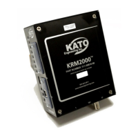
Describes the stationary receiver and its associated 24Vdc power supply.
Covers physical dimensions, receiver power, relay, and digital output parameters.
Details operating conditions, shock, vibration, and UL recognition.
Details DIN rail mounting options and requirements for the KRM2000 receiver.
Describes mounting for transmitter, loop antenna, and dipole antenna.
Details DIN rail mounting and cooling space requirements for the power supply.
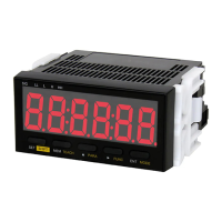
Details terminal connections and descriptions for the KRM2000 receiver.
Shows terminal connections for transmitter and loop antenna.
Illustrates power supply connections and the overall system diagram.
Explains the function and wiring of the receiver's three relay outputs.
Details the receiver's three digital outputs, including source/sink configuration.
Describes loop antenna output and available communication interfaces.
Explains transmitter wiring and details power supply wiring.
Illustrates the KRM2000 system's functional block diagram.
Explains how the system detects generator ground faults and monitors leakage resistance.
Describes loop tuning types and step size for optimizing antenna performance.
Details configuration of communication ports including USB and Bluetooth modules.
Details using the USB port for communication and firmware updates.
Explains EEPROM storage and initial protection features like service faults.
Details loop undervoltage, overcurrent, and radio link error protections.
Explains PWM re-enable time limit and optional diode fault monitoring.
Lists all data points monitored by the KRM2000 receiver, including voltage, current, and frequency.
Outlines routine inspection of wiring and long-term storage recommendations.
Provides a table of part numbers for KRM2000 system components.
Provides a table of symptoms, causes, and solutions for common KRM2000 issues.
Provides instructions for configuring TCP/IP settings for Ethernet/IP and other modules.
Step-by-step guide to configuring IP addresses using the Anybus IPconfig utility.
Explains the CIP object dictionary and instance attribute model for Ethernet/IP communication.
Indexes tables for unsigned 32-bit integer and floating point min/max values.
Details the general control register and indexes tables for part numbers.
Indexes tables for GPIO test mode enable and data min/max values.
Instructions for updating KRM2000 firmware using the C2Prog programmer.
Details wiring of the sensing filter and setting a 40kΩ offset in the receiver.
| Brand | Nidec |
|---|---|
| Model | Kato Engineering KRM2000 |
| Category | Measuring Instruments |
| Language | English |