16 | Kato Engineering, Inc.
4 Installation
This section describes the mechanical and electrical installation requirements for the KRM2000
TM
rotor monitoring system.
4.1 Mounting
The mounting requirements for the transmitter, receiver, inductive power loop antenna, power supply,
and the dipole antenna are described in this section.
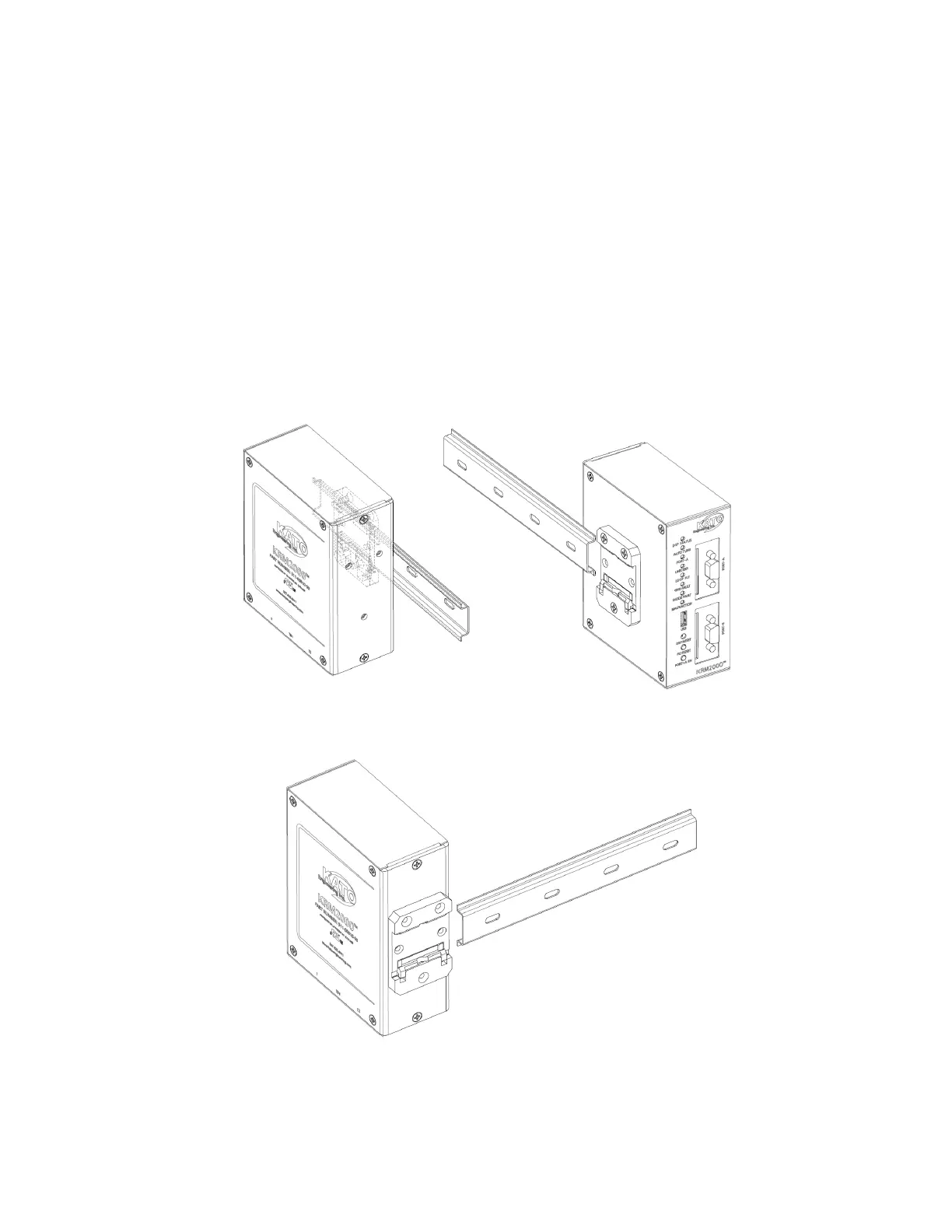
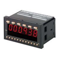
4.1.1 Receiver
The KRM2000
TM
receiver can be DIN rail mounted in the horizontal direction, with a minimum of 3” of
space from the terminal blocks to allow for easy removal. There are two optional locations for the
DIN rail mount, as shown in Figure 5 and 6.
Figure 5 Receiver DIN Rail Mounting Provision Option 1
Figure 6 Receiver DIN Rail Mounting Provision Option 2