34 | Kato Engineering, Inc.
7 Troubleshooting
This section provides the basic troubleshooting detail to follow if any issues occur during operation.
It should be noted that not all possible scenarios can be documented here, and if at any point the
issue can’t be resolved by the detail provided, please consult with the Kato Engineering service
department.
Table 5 Troubleshooting Guide
Link Error LED Illuminated
No data is being received from
the transmitter
Check inductive loop connections, verify that there is
loop voltage (>4Vrms)
Check radio dipole antenna connections
Check location of transmitter relative to the inductive
power loop
If Link Error persists, replace transmitter
Loop Fault LED Illuminated
Short circuit between loop
antenna pins of terminal block
Inspect the terminal block for a short
Disconnect inductive loop antenna leads from
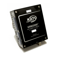
KRM2000
TM
receiver and check resistance between
Ground Fault LED Illuminated
Generator rotor has a ground
fault
Check resistance between generator field (-) and
ground (disconnect transmitter)
Ground fault resistance trip level
is set too high
Use GUI to monitor and/or change the ground fault
resistance trip level
Transmitter is malfunctioning
Test by placing resistor between generator field (-)
and ground, then use GUI to monitor the ground fault
resistance value
Illuminated
Diode fault detector malfunction
Use GUI to look at diode fault detector count 10
second average, if equal to, or below 5 then diode
fault detector is malfunctioning. Check connection
between diode fault detector and KRM transmitter,
check rotating rectifier diodes and replace diode fault
Diode Fault LED Illuminated
Use GUI to look at diode fault detector count 10
second average, if above 60 then diode fault
detector is indicating a diode fault. So, check rotating
rectifier diodes
NOTE: Diode fault LED flashing at a rate of 1 Hz is
the normal state of operation when a diode fault
detector is connected to the KRM transmitter and no
Malfunction Digital Output
Active (High) and/or Ground
Fault Relay Output Active
Excessive loop antenna current
Check causes listed for Loop Fault LED Illuminated
Check causes listed for Link Error LED Illuminated
DSP unable to tune loop
antenna
Check connection for open circuit between
KRM2000
TM
receiver and loop antenna
Loop antenna voltage is too low
Check loop for short circuit between loop antenna
and receiver
Monitor loop antenna voltage and loop under-voltage
set point with GUI
KRM2000
TM
receiver and
external monitoring system