19 | Kato Engineering, Inc.
4.2 System Connections
The following section demonstrates the terminal requirements as well as overall system connections
required for the KRM2000
TM
rotor monitoring system. Connections are to be made as instructed in
this manual and/or by any outside system drawings as governed by Kato Engineering only.
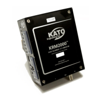
4.2.1 Receiver
Table 2 Terminal Connection Descriptions, Receiver
Ground fault signal output (source/sink)
Diode fault signal output (source/sink)
Malfunction signal output (source/sink)
Coax connector for receiver antenna
Communications port (Bluetooth)
Communications port (USB, see Note 1)
Note 1: See Kato Engineering for supported communication options.
Figure 10 Terminal Connections, Receiver