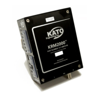
4.1.2 Transmitter
The transmitter is typically mounted on the diode wheel at the end of the shaft on the rotor. The
figure below shows the typical mounting requirements.
Black Wire
Connects to
Diode Wheel
DC minus –
Terminal
KATO
ROTOR MONITOR SYSTEM
Blue Wire Connects
to DC Plus Terminal
--Bus Partial View
Use Mounting Bolts M6-1x60 mm, 1/4x20x1.75, or
if spacer is used 1/4x20x3.00, Small Outline Flat
Washer, Locktite # 242 on Threads. Torque to 50
in lbs
Figure 7 Transmitter Mounting
4.1.3 Inductive Power Loop Antenna
The inductive power loop antenna is mounted to a loop antenna bracket, which is typically located on
the end frame at the exciter end of the generator. Various loops sizes are available to best fit the
application.
4.1.4 Dipole Antenna
The dipole antenna is mounted to the antenna bracket through a BNC connector. The antenna
bracket is found on the loop antenna bracket.