12 | Kato Engineering, Inc.
2.2.1 Inductive Power Loop Antenna
The loop antenna provides power to the rotor mounted transmitter through inductive coupling. The
loop antenna is powered by the receiver, which is connected through the loop antenna connection
block.
2.2.2 Dipole Receiver Antenna
The dipole receiver antenna is used to collect the data wirelessly from the rotor mounted transmitter
back to the stationary mounted receiver. This antenna is mounted to the loop antenna bracket, and
is connected to the receiver through BNC connectors and a coaxial cable.
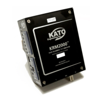
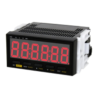
2.2.3 Receiver
The stationary mounted receiver collects the data from the rotor mounted transmitter through the
dipole antenna. The radio operates at 418MHz. The DSP based receiver is able to translate this
data and can indicate the status of the ground fault and diode fault (optional) detectors. Utilizing the
on board communications, the end-user can also collect data for diagnostic purposes.
2.2.4 Power Supply
The power supply provides 24 Vdc regulated power to the KRM2000
TM
receiver. The input power
range is 85 Vac to 263 Vac (50-60Hz), making it suitable for applications worldwide.
2.2.5 Transmitter
The transmitter is mounted on the shaft of the rotor, and is capable of monitoring the insulation
resistance between the brushless exciter, generator field, and the rotor shaft (ground). It also
measures the main field voltage and has an optional auxiliary channel for monitoring an optional
rotating diode fault detector. This data is transmitted wirelessly to the stationary receiver. The
transmitter is powered through the inductive loop antenna.