10 | Kato Engineering, Inc.
2.2 System Description
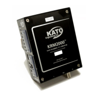
The KRM2000
TM
rotor monitoring system utilizes 5 components to provide the basic functions as
described previously.
(1) Stationary induction power loop antenna
(2) Stationary dipole receiver antenna
(3) Non-rotating receiver
(4) Power supply
(5) Rotor mounted transmitter
Figure 1 demonstrates these components and their general location. This diagram does not
demonstrate every application, but is provided as a generic guide to how the system is laid out.
WARNING: WHEN WORKING OR MOUNTING ANY COMPONENTS, MAKE SURE
THE PRIMEMOVER AND GENERATOR ARE NOT CAPABLE OF BEING ENERGIZED. USE
APPROPRIATE LOCK OUT/TAG OUT PROCEDURES. FAILURE TO DO SO MAY RESULT IN
SERIOUS INJURY.