25
●
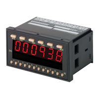
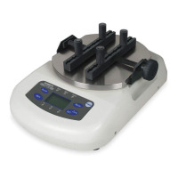
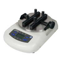
25. Option -BCD
When equipped with -BCD option, Binary Coded Decimal output is possible
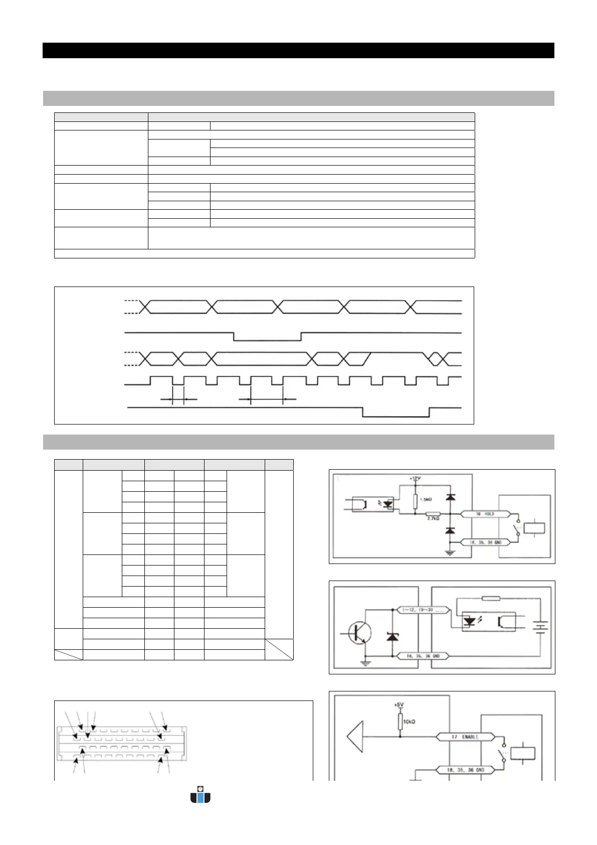
● Timing chart
Measured data
“00000” data 1
data 2
data 3 data 4
HOLD signal
“H”
“L”
BCD output
hold
“00000” “00000” data 1 data 2 data
3
high impedance
data
4
data
4
DT OUT signal
“H”
“H”
“L”
“L”
data out
renewal
ENABLE signal
about
6 msec
about
100 msec
Model -BCD
NPN Open collector output Output capacity 30VDC●20mA
Open collector input
Open collector (NPN) input
LO input
Load capacity : minimum 5mA
0 ● 1.5V
HI input Leakage current : maximum 0.1mA
Data output 6 digits BCD code
Decimal point output DP1 ● 4 ●1 ● 4 digits after decimal point●
Control output
PLUS When output data is positive, PLUS turns to LO
DT OUT When DATA OUT is HI, output signal is set
OVR When displayed value overows, OVR turns to LO
Control input
HOLD While HOLD is LO, output data does not renew
ENABLE While ENABLE is LO, output has high impedance
Connector
Meter :PCS-E36LMD/ Accessory side: ●Plug● PCS-E36FS●●Cover● PCS-E36LA
(Both manufactured by HONDA TSUSHIN KOGYO CO., LTD.)
Positive-logic-negative-logic available for BCD and decimal point output (opted at Function 10)
● Cable connection is to be done by users.
in/out Code ●●Pin number Code in/out
Out
put
×10
0
1 1 19 1
×10
3
Out
put
2 2 20 2
4 3 21 4
8 4 22 8
×10
1
1 5 23 1
×10
4
2 6 24 2
4 7 25 4
8 8 26 8
×10
2
1 9 27 1
×10
5
2 10 28 2
4 11 29 4
8 12 30 8
PLUS 13 31 DP1
DT OUT 14 32 DP2
OVR 15 33 DP3
Input
HOLD 16 34 DP4
ENABLE 17 35 GND
GND 18 36 GND
Connector numbering
(as the plug is viewed from wire connection side)
1 2 3 4 ●17● 18
19 20 35 36
●
1. Specications for -BCD Option
●
2. Connection for -BCD Option
HOLD input circuit
Output circuit
ENABLE input circuit
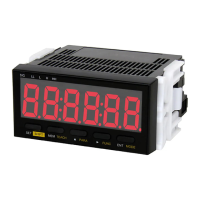
Tachometer
Tachometer
Tachometer
● The connector next to “1”marking
is #2 terminal.
● Suggested wiring order is 1● 3●
5 ● 20● 22● 24 ● for the ease
of nding the right numbering.
●
Please use extra caution in soldering,
as the clearance is small.
Attachment
example
Attachment
example
Attachment example
OUTPUT
www.calcert.com sales@calcert.com1.888.610.7664
0
5
10
15
20
25
30
 Loading...