Do you have a question about the Nidek Medical RS-3000 and is the answer not in the manual?
General precautions for servicing and maintenance procedures, including personnel qualifications and handling.
Cautions for handling equipment during maintenance, including dropping parts and using tools.
Troubleshooting steps for when the pilot lamp of the isolation transformer does not light up.
Troubleshooting steps for when the main body of the device does not start properly.
Troubleshooting steps for when the anterior eye is not displayed.
Troubleshooting steps for when the PC does not start properly.
Troubleshooting for the image capturing unit not moving smoothly along the base unit.
Troubleshooting for the joystick not moving the image capturing unit up or down.
Troubleshooting for when the chinrest does not move.
Troubleshooting for when images cannot be captured.
Troubleshooting for the motorized optical table not moving up or down.
Procedure for removing various covers from the main body of the device.
Procedure for removing the isolation transformer cover.
Procedure for removing PC covers.
Procedures for replacing components of the main body.
Procedures for replacing parts of the isolation transformer.
Procedures for replacing PC components.
Procedures for replacing parts of the motorized optical table.
Description of different operational modes.
Procedure for checking the anterior eye illumination.
Instructions for setting switches on circuit boards.
Procedure for loading the OCT calibration file.
Procedure for upgrading the device software version.
Procedures for checking error logs.
Configuration settings for the PC.
Maintenance procedures for the motorized optical table.
Visual overview of the system configuration.
Schematic diagram showing the electrical wiring of the system.
Detailed diagrams of various connector cables.
Diagrams showing switch positions on circuit boards.
List of adjustable parameters and their settings.
List of error codes, their contents, and main causes.
Diagrams illustrating the layout of assemblies and boards.
Table indicating required parts and adjustments for maintenance tasks.
Reference list of screws used in the device.
| Light Source | Superluminescent Diode (SLD) |
|---|---|
| Wavelength | 880 nm |
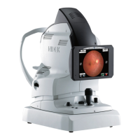
| Model | RS-3000 |
| Scan Depth | 2.3 mm |
| OCT Resolution (Axial) | 3 μm (in tissue) |
| OCT Resolution (Lateral) | 20 μm |
| Connectivity | Ethernet |
| Manufacturer | Nidek Medical |
| Technology | Optical Coherence Tomography (OCT) |
| Axial Resolution | 3 μm (in tissue) |
| Display | 15-inch LCD |
| Power Requirements | AC 100-240V, 50/60Hz |
| Scan Width | 6 x 6 mm, 8 x 8 mm, 10 x 10 mm, 12 x 12 mm |
