VBA22001-R.3754.A
-A135 ・ D700-
(8) Pixel defect compensation - black point
Using the color viewer (LV13 equiv.) and tool lens (F5.6), pictures are taken. When pixels of which the output
level is under specied value are detected, the coordinates of the detected pixels are additionally written as pixel
defect compensation data.
(9) Pixel defect compensation - white point
Pictures are taken on the blackout surface (against dark background). In case the pixel output is found to
be beyond the standard value, the detected pixel coordinates are additionally written as the pixel defect
compensation data.
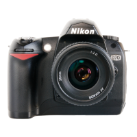
(10) Tilted sensor inspection & adjustment
This checks whether the indications of the virtual horizon display of the camera match the shot image, and make
necessary adjustments.
SETUP
①
Place the tilted sensor checking chart so that the chart line becomes vertical by using weighted string, etc.
[Enlarge a A4 (size) chart of the repair manual with a copier to become A3 (size), and use it.]
②
Attach the AF50/1.4D lens to the camera. Set AF mode to
"
M
"
, focus ring to
"
0.7m
"
.
③
Set the camera in front of the chart approx. 0.7m-distance away.
④
Check the virtual horizon display, and place the camera at the horizontal position.
Make the inspection by start button, while make the adjustment by adjustment button.
(Angle offset standard: from "-1 deg." to "+1 deg.
)
※
Green letters mean "up to standard", while red means "NOT up to standard)
Device
BODY CAP
Device
COLOR VIEWER
J63070
D1 STANDARD LENS
J61185
approx. 0.7
m
Tilted sensor checking chart
AF50/1.4D
Mounting surface of Image-PCB
August, 19,2008
Changed page (Overall revision)