Do you have a question about the Nikon DTM-350 and is the answer not in the manual?
Describes symbols used for safety instructions in the manual.
Lists critical warnings for safe operation and handling of the instrument.
Lists important cautions to prevent injury or damage during use.
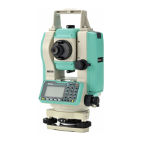
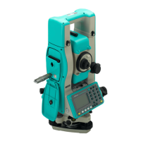
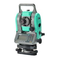
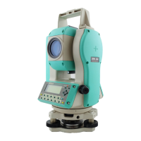
Identifies and describes the main parts of the instrument.
Details procedures for setting up and preparing the instrument for use.
Explains the instrument's display elements and button functions.
Covers initial setup steps like inputting point names and codes.
Guides users through turning the instrument on and off.
Details various measurement and calculation functions.
Describes checking and adjusting the instrument's plate level.
Covers checking and adjusting the circular level.
Explains the checking and adjustment of the optical plummet.
Details checking and correcting angle errors.
Describes how to check and maintain the instrument constant.
Provides detailed specifications for the instrument's main components.
Lists the included accessories and parts.
Describes the specifications and cautions for the connector.
Illustrates the interconnections of the instrument and its accessories.
Details data transfer and connection procedures.
Lists common recording errors and their solutions.
Covers errors related to point searching and actions.
Details errors and actions specific to the Stakeout function.
Lists errors encountered in the Job Manager and their resolutions.
| Model | DTM-350 |
|---|---|
| Category | Total Station |
| Angle Accuracy | 5" |
| Telescope Magnification | 30x |
| Operating Temperature | -20°C to +50°C |
| Angle Measurement Method | Absolute |
| Minimum Reading | 1" |
| Compensator | Dual axis |
| Display | LCD |