13
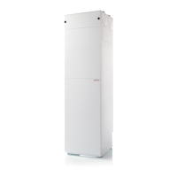
Positioning the unit
The unit makes little noise and it produces only weak vibrations, but you should still take into account potential vibrations that can
spread from the unit to individual building components. There should be approx. 10 mm distance to other building components and to
permanent fixtures.
5. Sensor and humidity sensor are pulled down through
the tulle in the shelf on the left side of the unit.
ATTENTION! The T1 sensor, which is located in the shelf
on the right side (together with the USB connector), must
be pulled down through the tulle.
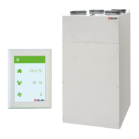
6. The plug of the USB cord is pulled out of the board,
after which it can be pulled through the tulle.
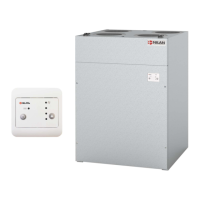
7. Unscrew the 4 wires from the terminals for the bypass
motor.
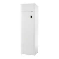
8. The bypass box is pulled out.
Then push the 8-pole plug into the duct for the fan part.
9. Remove the 6 pcs. screws on the bottom. 10.The top is lifted by the lower part.
ATTENTON
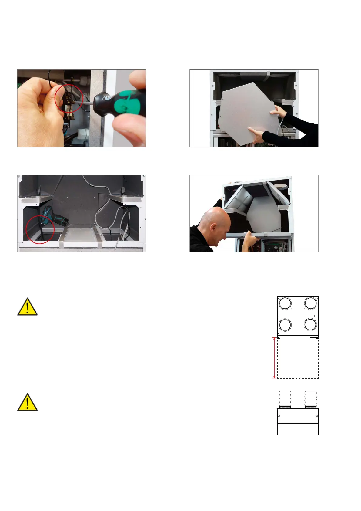
A free space is recommended in front of the ventilation unit of at least 60 cm.
It must be easy to replace filters and e.g. it must be possible to remove the exchanger, re-
place the fan or other components.
The unit must be level to enable proper drainage from the condensate tray.
ATTENTON
When replacing or servicing certain components, such as fans, you will need to remove the
top of the unit. In order to make the top of the unit easily removable, flexible
connectors should be fitted between the unit and the ducts.
If flashings are fitted above the unit, these must be easily removable.
Recommended min. 60 cm
13
42