Scrub System 161Service Manual – Advance 7765 / Nilsk CR1500
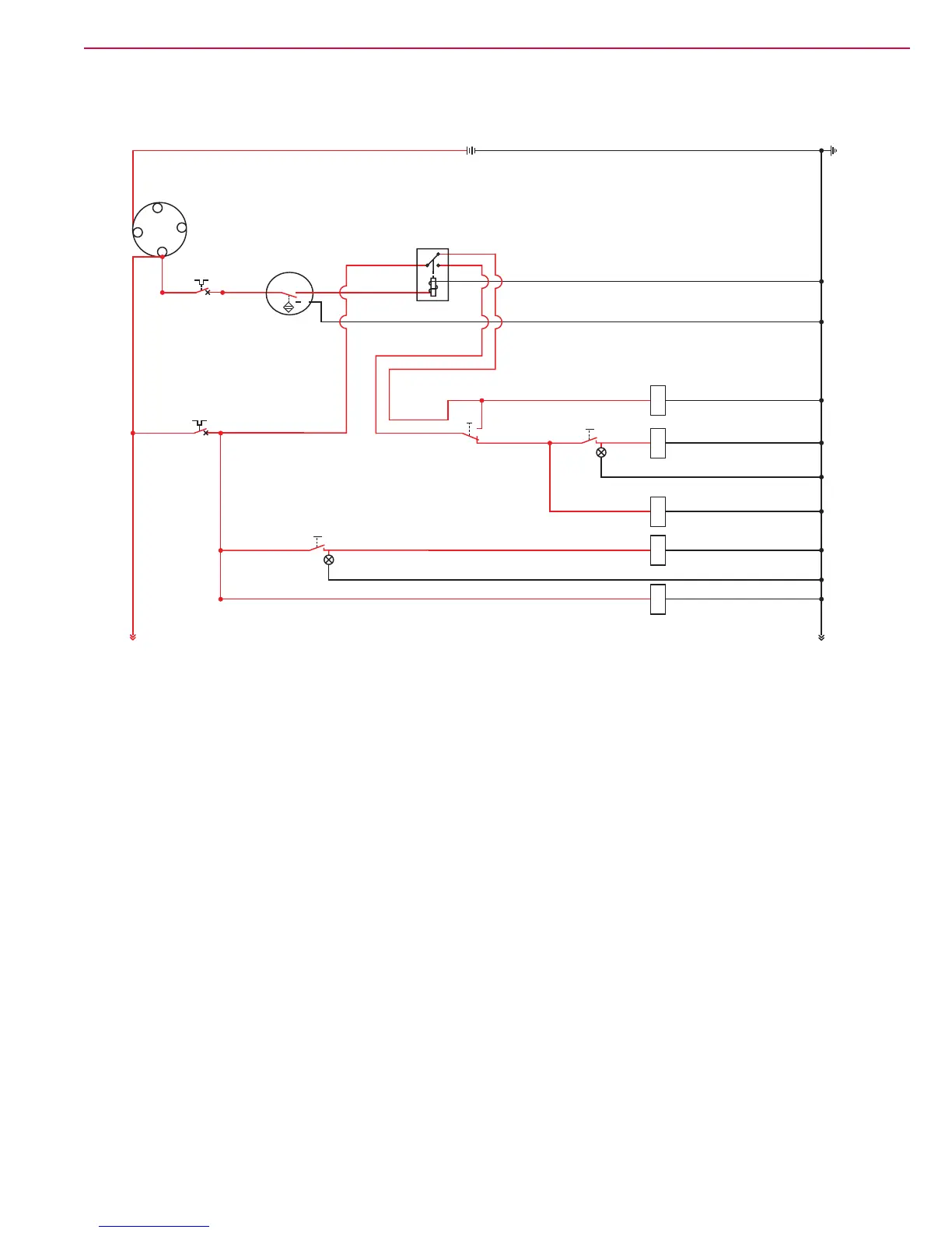
Scrub System Wiring Diagram
Circuit Descriptions
Scrub Brush Motors
The Normal Rotation Brush (4) solenoid valve in the main control valve controls the oil ow to the scrub
brush motors. The scrub brush motors will run when the Ignition Switch is on, the Drive Pedal Forward Sensor
switches to position 2 to energize the Forward Relay R4 coil, the Forward Relay R4 contacts switch to the 87
(Lower) position and the Scrub Brush Switch on the instrument panel is switched on.
The Brush Rotation Switch on the instrument panel controls the Reverse Rotation Brush (3) solenoid valve
which controls the rotational direction of the scrub brush motors.
• When the Brush Rotation Switch is set to the top (forward) position, the Reverse Rotation Brush (3) solenoid
is de-energized to allow the scrub brush motors to run in the normal (forward) direction.
• When the Brush Rotation Switch is set to the bottom (reverse) position, the Reverse Rotation Brush (3)
solenoid is energized and reverses the direction of the oil ow to the scrub brushes. This runs the scrub
brushes in reverse and lights the Brush Rotation Switch.
Also refer to the Scrub System Hydraulic Diagrams section.
Scrub Brush
Switch
Brush
Pressure Switch
Raise
Lower
CB7
15 A
15 A
7 18 58
7
2
30
87 1
2
12
3
46
46
40
403
43
43
87a
1
Scrub Brush Solenoid (6)
Scrub Brush Solenoid (8)
Normal Rotation Brush (4)
1418
Reverse Rotation Brush (3)
18
Scrub Brush Lock Up Solenoid (9)
7
B-
7
Brush
Rotation Switch
12
3
Battery 12 VDC
+
-
Bat.
Ignition
Switch
R4
Forward Relay
Drive Pedal
Forward Sensor
12 56
12
3
46
85
86
CB5
2
1
87a
87