H
Nilfisk
ALTO
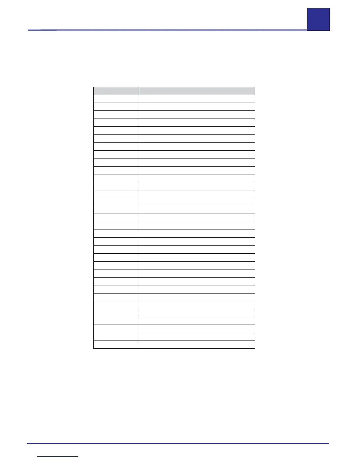
1. Wiring diagrams parts list
Table H.1: Wiring diagrams parts list for Neptune 4
Note: The components listed in Table H.1 relate to the following Neptune 4 wiring diagrams.
Code Component designation
A1 Control board
A3 Starting electronic
B1 Temperature sensor
B2 Reed switch
B3 Thermo fuse
B4 Microswitch
B6 Float switch, pump oil
B7 Flame sensor
B8 Float switch, AntiStone
B9 Float switch, fuel
C1 Capacitor
C2 Starting capacitor
F1 Pico fuse
F2 / F3 Fine-wire fuse
K1 Contactor
K2 Relay
K3 Klixon relay
M1 Motor, three-phase
M2 Burner fan motor
MT Thermal protector
R1 Discharge resistor
R2 Inrush current limiter
S1 Switch on / off + temperature setting
S2 Switch star / delta
T1 Transformer
T2 Ignition transformer
X1 Flat connector
X2-X4 Terminal block
X5 Plug connector, 5-way, datalogger
X11 – X13 Omnibus terminal
Xma-b Motor connector
Y1 Solenoid valve
Wiring diagrams
Neptune 4_EN_Ver.1.0_04/06
 Loading...