EasyManua.ls Logo

Nilfisk-ALTO Scrubtec R 6-100 40D - User Manual

Nilfisk-ALTO Scrubtec R 6-100 40D
93 pages
Print Icon
To Next Page IconTo Next Page
Loading...
08/12 Updated 08/14 Form No. 56043159
Service Manual
Clarke
®
model numbers:
56114000 Focus II Rider 28 D Base
56114001 Focus II Rider 34 D OBC Base
56114002 Focus II Rider 34 D Base
56114003 Focus II Rider 28 B Base
56114009 Focus II Rider 28 B OBC Base
56114010 Focus II Rider 28 D OBC Base
Nilfisk-Alto model numbers:
56114004 Scrubtec R 6-71 28D
56114005 Scrubtec R 6-71C 28C
56114006 Scrubtec R 6-86 34D
56114008 Scrubtec R 6-100 40D
English
Clarke Focus II Rider Autoscrubber
Nilfisk-Alto Scrubtec R6 Rider Autoscrubber

Table of Contents

Question and Answer IconNeed help?

Do you have a question about the Nilfisk-ALTO Scrubtec R 6-100 40D and is the answer not in the manual?

Nilfisk-ALTO Scrubtec R 6-100 40D Specifications

General IconGeneral
ModelScrubtec R 6-100 40D
CategoryFloor Machine
BrandNilfisk-ALTO
Brush Pressure40 kg
Noise Level68 dB(A)
Brush Motor2 x 750 W
Voltage36 V
Working Width1000 mm

Summary

General Information

Service Manual Purpose and Application

Provides info on machine operation, troubleshooting, and maintenance.

General Safety Instructions

Operating and Servicing Precautions

Covers safety warnings, cautions, and specific instructions for safe operation and maintenance.

Transporting the Machine

General Specifications

Maintenance Schedule

Diagnostic and Service Tools

PM Checklist

Operational Inspection Items

Lists operational checks with defect codes for inspection.

Visual Inspection Items

Control System

Control Panel Overview

Details the components and functions of the machine's control panel.

Control System Functions

Main Machine Controller

Describes the main electronic control board and its functions.

Main Machine Controller Programming

Programming Menu Outline

Lists parameters that can be programmed via the hidden menu system.

Navigating the Hidden Menus

System Status and Diagnostics

Service Test Mode

Provides access to test machine outputs and monitor inputs.

Main Controller Error Codes

Service Test Mode

Test Mode Functions

Details how to exercise motors and solenoids using test mode.

Removal and Installation

Main Control Board

Provides steps for removing and installing the main control board.

Solution Valve, Filter, and Solenoid

Provides steps to remove and replace solution valve, filter, and solenoid.

Electrical System

Safety Circuit

Details the series of switches acting as a safety circuit.

Onboard Battery Chargers

Delta-Q Charging Profiles

Maintenance and Adjustments

Charging Batteries

Provides safety precautions and procedures for charging batteries.

Troubleshooting

Battery Testing

Explains methods to test batteries for dead cells.

Specifications

Wiring (Ladder) Diagram

Wiring Harness Diagram (Early)

Wiring Harness Diagram (Late)

Main Machine Controller Connectors

Options and Accessories

Recovery System

Vacuum Motor Control Circuit Overview

Troubleshooting Vacuum System

Vacuum Suction Test

Vacuum Motor Removal and Installation

Recovery System Specifications

Scrub System Overview

Functional Description

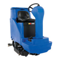
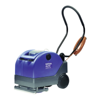
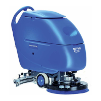
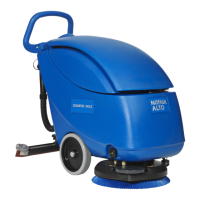
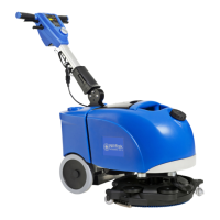
Describes machine configurations with different scrub deck types and sizes.

Scrub Deck Types

Scrub Deck Motors Circuit Overview

Deck Lift Actuator Operation

Maintenance and Adjustment

Lift Actuator Limit Adjustment

Provides steps to adjust the limit switches of the lift actuator.

Scrub Deck Removal and Installation

Deck Lift Actuator Removal and Installation

Brush Motor Contactor

Disc Deck Motor

Cylindrical Deck Motor

Boost Deck Motor Removal and Installation

Scrub System Specifications

Solution System

Solution System Circuit Overview

Detergent Pump Removal and Installation

Solution System Specifications

Squeegee System

Squeegee Maintenance and Adjustment

Actuator Limit Adjustment

Front Squeegee Blade Reversal or Replacement

Squeegee Lift Actuator Removal and Installation

Wheel System, Non-Traction

Wheel System, Traction

Functional Description

Describes the traction wheel system and its components.

Drive Motor System Function

Wheel Drive Controller J10 Pinout Functions

Troubleshooting Wheel System

Wheel Drive Controller Error Codes

Drive Controller

Removal and Installation

Provides steps for removing and installing the drive controller.

Drive Wheel Assembly Removal

Drive Wheel Assembly Reassembly Notes

Drive Motor, Brushes, and Electromechanical Brake

Drive Motor Service

Carbon Brushes Replacement

Details the replacement of carbon brushes in the drive motor.

Electromechanical Brake Replacement

Details the removal and replacement of the electromechanical brake.

Drive Tire Replacement

Drive Tire Replacement Notes

Steering Chain Service

Wheel System Specifications

Special Tools

Curtis 1311 Programmer

Describes the Curtis 1311 Programmer for diagnostics.

Related product manuals