Control System 16Service Manual – Focus II / Scrubtec R6 Rider Autoscrubber
Control System
Functional Description
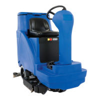
Within the Focus system there are two primary controllers: the Main Machine Controller (A1) and the
Wheel Drive controller (A2). The Main Machine Controller controls the primary machine functions, and the
Wheel controller controls the drive functions. The Wheel controller communicates with the Main Machine
Controller to inform the Main Machine Controller of machine movement status.
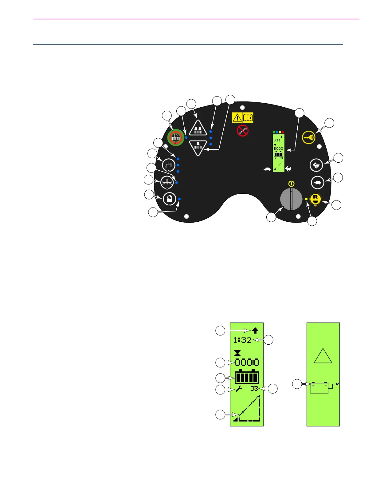
Control Panel
The control panel (display) is an
integral component with the Main
Machine Controller (A1) circuit board.
Key Switch (A): The key switch
serves as a main control switch to
enable or disable operation of the
machine. The key is removable to
prevent unwanted operation when
not in use. The key switch doesn’t
disconnect any power circuits, but
instead, sends a signal to both the
Main Machine Controller and Wheel
Drive controller to indicate the On/Off
function.
Reverse Switch (C) and Indicator
(B): The reverse switch activates a toggle function within the Main Machine Controller. The Main Machine
Controller then sends a reverse command to the Wheel controller by pulling the (J3-3) output high. When
the Indicator (B) is lit, pressing down on the foot pedal will cause the machine to move in reverse.
Speed Increase/Decrease Switches (D & E): These switches set the upper speed limit of the machine
for the full throttle position. The machine speed limit is controlled within the Main Machine Controller,
and the Main Machine Controller communicates this setting to the Wheel controller. For Wheel controllers,
the speed limit function is typically controlled with a 3-wire potentiometer. The Main Machine Controller
contains an electronically controlled potentiometer.
Graphic Display (F): Machine operation information is presented to the operator on the graphic display.
F1: Detergent Strength Indicator (for detergent systems only).
F2: Detergent Ratio (for detergent systems only).
F3: Hour meter (total use of the machine)
F4: Battery Indicator
F5: Fault Indicator
F6: Fault Code
F7: Speed Limit Indicator
F9: Battery Low Screen
Horn Switch (G): Activates the horn
Scrub On/Off Switch (M): Pressing this switch will toggle the scrub system on and off. When active, the
scrub deck will lower for the Deck Down Time. When the machine begins to move, the squeegee will lower
G
E
D
C
B
A
H
J
K
L
M
N
O
Q
P
R
S
F
!
F1
F2
F7
F3
F4
F5
F9
F6
 Loading...