Solution System 68Service Manual – Focus II / Scrubtec R6 Rider Autoscrubber
Circuit Overview
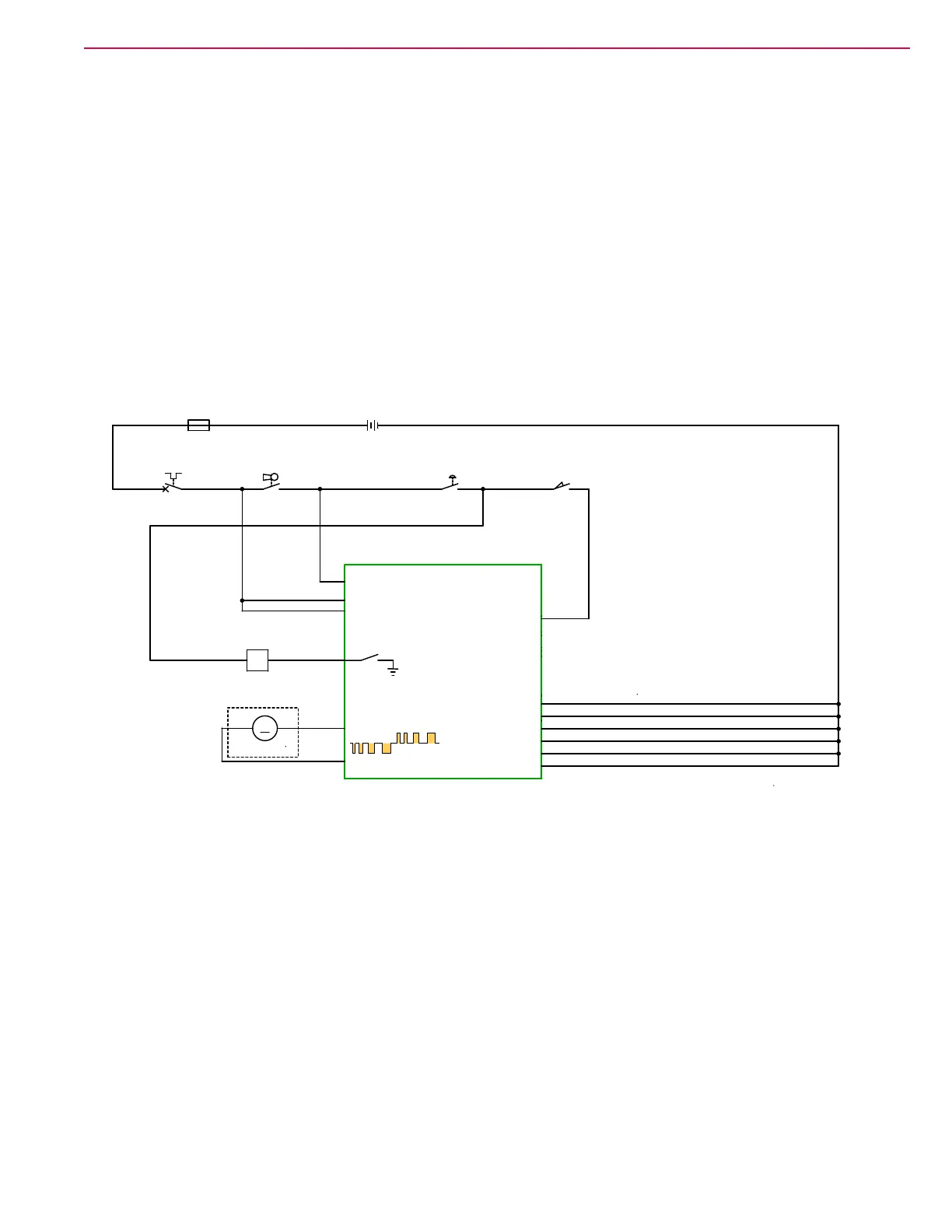
Solenoid Valve Circuit
The positive terminal (white/brown wire) of the solution solenoid receives +24V battery power through key
switch and E-stop switch. The negative terminal (violet/black wire) of the solution solenoid is connected to
the Main Machine Controller at J3-11. The solenoid is active when the controller forces the J1-11 terminal
to Battery Negative. The solenoid output is inhibited unless the machine is in motion or pre-wetting is called
for.
Detergent Pump
The detergent pump is a small reversible diaphragm pump. The polarity of the pump is reversed to cycle the
pump faster. The ow rate of the detergent pump is controlled by PWM at varying rates depending on the
desired mixing ratio.
Solution System Schematic
A1
MAIN MACHINE
CONTROLLER
J3-1 B+
J3-8 B+
J3-14 KEY SWITCH
SEAT
SWITCH J3-4
S1
KEY SWITCH
1 2
BT1
BATTERY, 24 VDC
+ -
L1
SOLUTION SOLENOID VALVE
1 2
CB2
CIRCUIT BREAKER
10 AMP
12
E-STOP
SWITCH
S4
1 2
S2
SEAT SWITCH
21
F1
FUSE, 150A.
1 2
OPTIONAL
B- J1-8
B- J2-8
B- J2-7
B- J2-1
B- J2-2
B- J3-2
M
M2
DETEGENT PUMP
+-
Reversible PWM
 Loading...