Wheel System, Traction 78Service Manual – Focus II / Scrubtec R6 Rider Autoscrubber
Wheel System, Traction
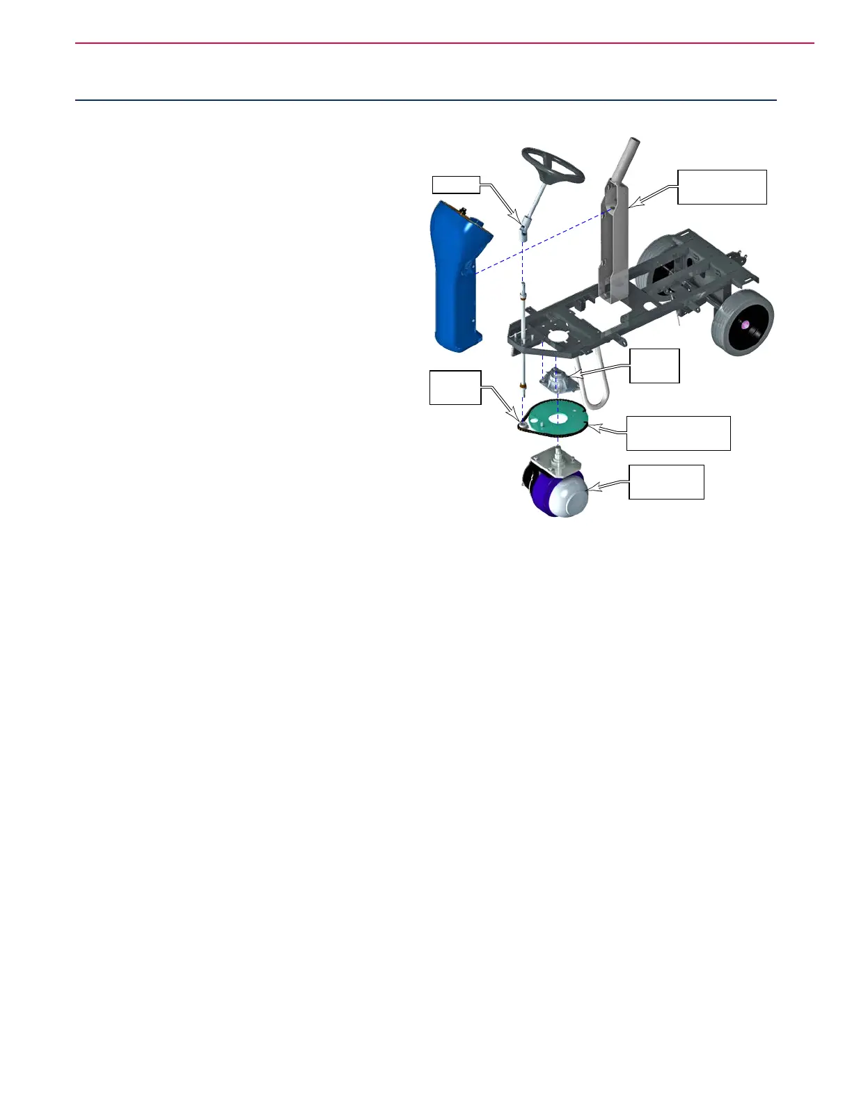
Functional Description
The drive system of the Focus machine consists of a
single drive wheel with an integral motor. The drive
wheel connects to the subframe with a rotational
bearing and ange to provide steering rotation.
Steering control is made through the steering column
that passes through a universal joint to translate the
rotation from the angled steering wheel to the vertical
shaft and pinion sprocket. The pinion sprocket drives
a chain that wraps around the steering sprocket. The
steering sprocket has no chain teeth, but the chain
is xed to the sprocket at the ends of the chain using
standard master links.
Drive Pedal Sensor
The drive pedal sensor (R1 pot) is a variable resistor
connected to the Pin-4 input of the wheel drive
controller, with pins 3 and 13 as reference voltages.
As the resistance changes, the wheel drive controller
increases or decreases drive motor speed.
For the Focus drive system, the drive pedal sensor is
not set up in a wig-wag conguration, where drive
direction is controlled by a single potentiometer. Instead, the forward/reverse function is independently
controlled by a separate control line between the Main Machine Controller and the Wheel Drive controller.
Moreover, the speed-limit function is also controlled by the Main Machine Controller and transmitted to the
Wheel Drive controller on a separate control line.
In this conguration, the drive pedal sensor is a simple resistive circuit that tells the Wheel Drive controller
the appropriate percentage of power to provide to the drive motor. The remaining drive functions are
controlled by the Main Machine Controller through the Wheel Drive controller.
Speed Limiting Potentiometer
To give the operator better control over the machine in operation, the Wheel Drive controller has a variable
maximum speed limit for full pedal deection of the throttle potentiometer. This task is commonly performed
with a physical potentiometer in parallel with the drive pedal potentiometer. However, on the Focus system,
this speed limiting function is governed by the Main Machine Controller. The Main Machine Controller
contains an electronically controlled, solid state potentiometer to provide this speed limit signal to the Wheel
Drive controller.
Steering
Column Frame
U-Joint
Bearing
Flange
Steering Sprocket
and Chain
Drive Motor
and Wheel
Pinion
sprocket
 Loading...