Electrical System 30Service Manual – Focus II / Scrubtec R6 Rider Autoscrubber
Electrical System
Functional Description
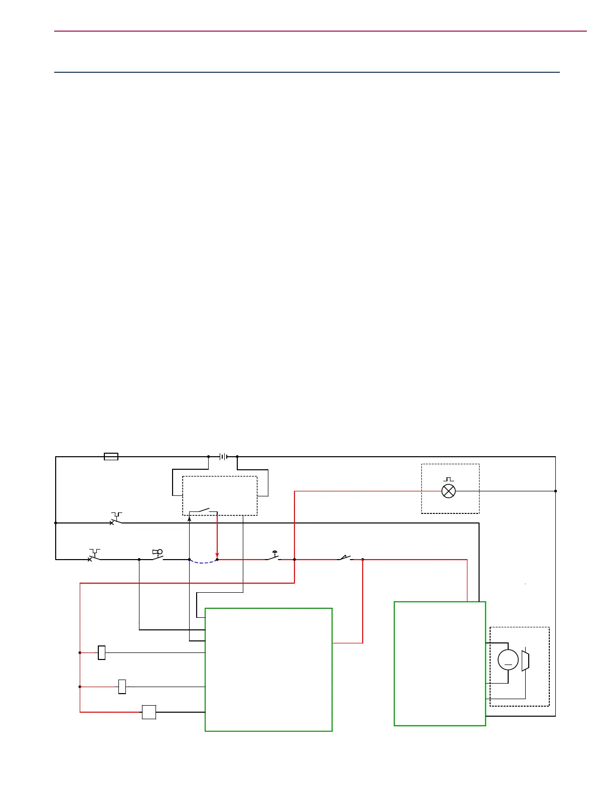
The Focus II machine is powered using four, 6-volt batteries connected in series, for a total system nominal
voltage of 24 volts. To protect the batteries from over discharge, the system is protected with a 150 amp fuse
(F1). With the exception of the optional on-board battery charger, all other connections are downstream
from this main fuse.
There are 2 resettable circuit breakers that protect the electronics. A 70 amp circuit breaker (CB1) protects
the Wheel Drive Controller (A2). A 10 amp circuit breaker (CB2) protects the Main Machine Controller.
The brush contactor coil, vacuum contactor coil, and solution solenoid are also downstream from this circuit
breaker. If these circuit breakers trip, their respective button will pop up. Pressing the button back in after
the overload has cleared will reset the breaker.
Safety Circuit
A series of switches acts as a safety circuit to prevent certain machine operations under different conditions.
The easiest way to describe their function is from last to rst, because each upstream switch does the same
thing as all downstream switches, but removes slightly more functionality.
The last of these is the seat switch. When the seat switch is open (no operator on seat), then control power
is removed from the Wheel Drive controller. The Main Machine controller still has power, but the software
is notied that the seat circuit (or E-stop) is open. The E-stop is similar to the seat switch, except it also
disables power to several key components, such as the brush and vacuum contactor coils, the solution
solenoid, and the optional ashing light. When an optional onboard battery charger is present, its internal
interlock switch disables the same components as the E-stop, and opens the circuit whenever the charger is
operating (plugged in to power).
The rst switch in the circuit is the main key switch. It disables the same functions as all other switches
downstream from it, but also disables most of the control power to the Main Machine controller too. The
Main Machine controller always has some power (unless the batteries are disconnected).
A1
MAIN MACHINE
CONTROLLER
OPTIONAL ON BOARD
BATTERY CHARGER
B+ B-
Interlock
PIN 14 - BRAKE +
PIN 5 - KSI
B+
B-
M1
M2
A2
CURTIS 1228 SPEED
CONTROLLER
J3-14 KEY SWITCH
J3-12 VACUUM
CONTACTOR
J3-13 BRUSH
CONTACTOR
J3-11 SOLUTION
SOLENOID
SEAT
SWITCH J3-4
J2-3 BAT CHARGER
ON BOARD COMMUNICATION
3 4
3 4
S1
KEY SWITCH
1 2
BT1
BATTERY, 24 VDC
+ -
L1
SOLUTION SOLENOID VALVE
1 2
M
M1
WHEEL
DRIVE
MOTOR
-
+
CB2
CIRCUIT BREAKER
10 AMP
12
K2
BRUSH CONTACTOR
LP1
Optional Flashing
Lamp
1 2
Y1
BRAKE
1
2
CB1
CIRCUIT BREAKER, 70A.
12
E-STOP
SWITCH
S4
1 2
S2
SEAT SWITCH
21
K1
VACUUM CONTACTOR
F1
FUSE, 150A.
1 2
21 3
W/O Charger
Jumper
 Loading...