14
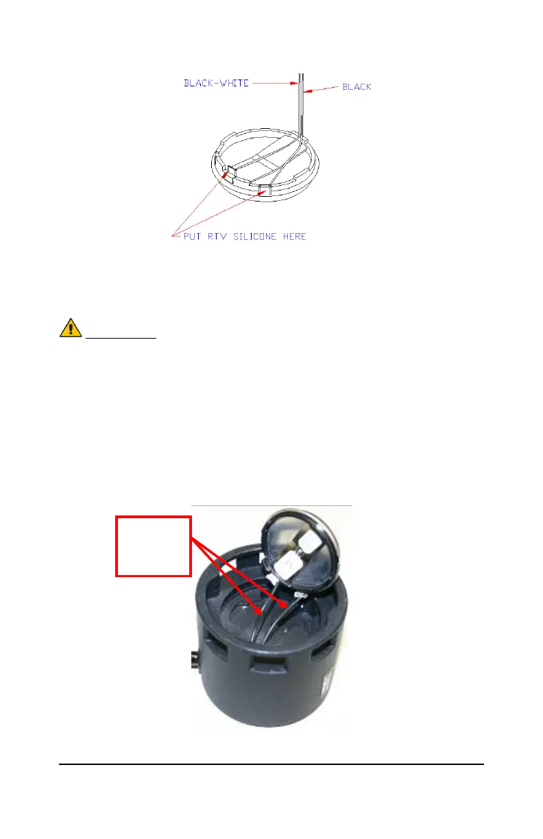
angle bend as shown in Figure 10.
Figure 10: Transducer Wire Positioning
7.5 Add two small beads of RTV silicon to fasten the spade connectors to
the transducer terminals.
CAUTION:
Do NOT allow the RTV to contact any part of the transducer,
except the wire connection tabs. This will affect the
transducer performance.
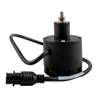
7.6 Lay the transducer wires in place so they sit in the two slots cut on
the bottom of the sensor housing (Figure 11).
7.7 Position the transducer so it sits flat in the sensor casing. The
transducer should not rock back and forth and should be flush with
the top edge of the cut-out once it is properly seated in the casing.
Figure 11: Slots for the Transducer Wires
Slots for
the wires
to
lie in


 To Next Page