23
11 Appendix A – Adjusting 44730 Calibration Stand
11.1 Tools Required:
2 x 9/16 Wrenches
1 x 24” Square
1 x Tape Measure
1 x Pliers
11.2 With the sensor stand fully assembled, place it on a flat surface
standing on end.
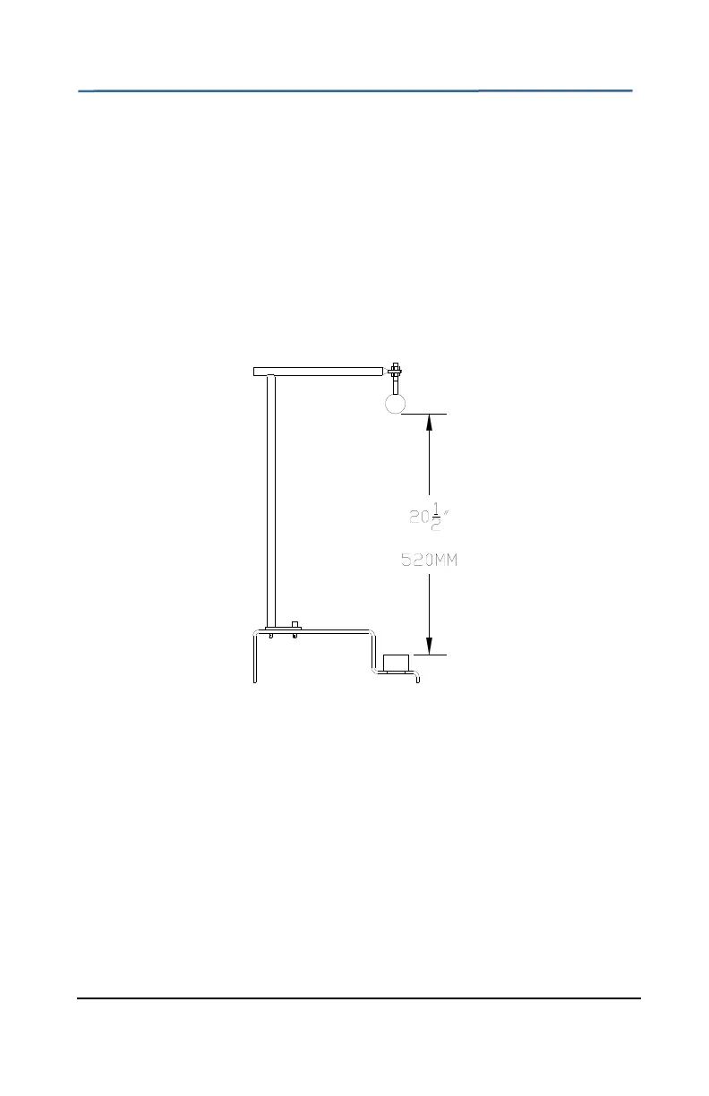
11.3 Loosen the nuts holding the ball target and adjust until the bottom
surface of the ball is 20.5” from the sensor mounting ring. (Figure
12)
Figure 12: Distance from Ball Target to Mounting Ring
11.4 Tighten the ball target nuts.
11.5 Using a 24” square, place the base of the square on the sensor
mounting ring as shown in Figure 13. The side of the ball should be
aligned ~1/16” (1.5mm) in from the inside edge of the sensor
mounting ring. Check both sides of the ball target. If the ball is not
aligned bend the ball mounting arm until alignment is achieved. Align
the ball to within +/-1/16” (+/-1.5mm).


 To Next Page