WWW.NORAC.CA
PRECISIONDEFINED
Page14
Visitwww.solutions.norac.caformoresystem
installationandtroubleshootinginfo.
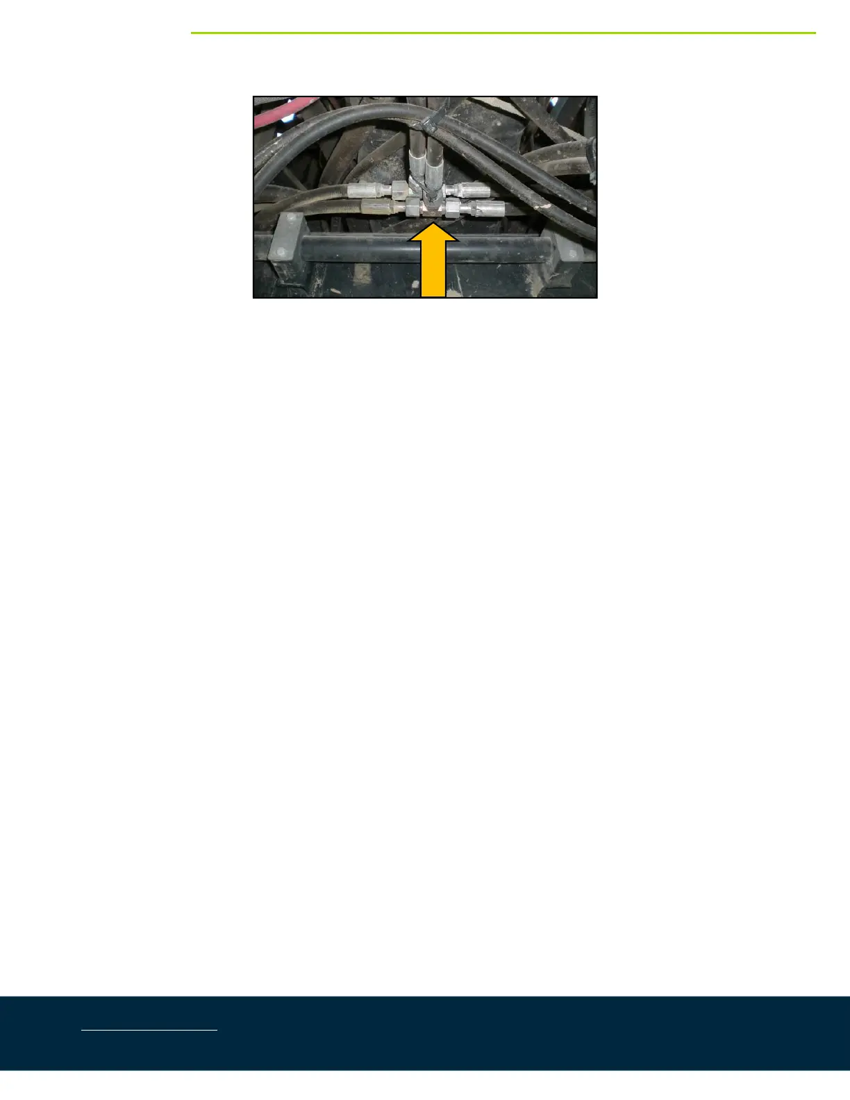
Figure8:CaseMainLiftTeeLocation
12. DisconnecttheraisehosethatrunsfromtheCasevalve blocktothemainliftteeandinstallthe6FORX‐
6MORTfitting(*F03).Reconnecttheraisehosetothetee.
13. ConnecttheNORAChose(H05)thatisconnected tothe“B”portonthe3
rd
stationoftheNORACblockto
theteefitting(*F03).
14. DisconnectthelowerhosethatrunsfromtheCasevalveblocktothemainliftteeandinstallthe6FORX‐
6MORTfitting(*F03).Reconnectthelowerhosetothetee.
15. ConnecttheNORAChose(H05)thatisconnected tothe“A”portonthe3
rd
stationoftheNORACblockto
theteefitting(*F03).
16. Installfour(4)6MOR‐6FORX90fittings(F14)ontothe6FORXR‐6MORTtees(F13).
17. ConnecthoseH06betweentheF14fittingsonthelower(“A”)lines.
18. ConnecthoseH06totheF14fittingontheleftraise(“B”)line.
19. ConnecthoseH07totheF14fittingontherightraise(“B”)line.
20. Installfour(4)6MB‐6MORfittings(F12)ontotheportsonthewingrollcylinder(H20).
21. Installfour(4)6MOR‐6FORX90fittings(F14)ontotheF12fittingonthewingrollcylinder(H20).
22. Connecthose H07 from the right raise line to the outer port on the cable end of the wing roll cylinder
(H20).
23. ConnecthoseH06fromtheleftraiselinetotheouterportontheoppositeendofthe wingrollcylinder
(H20).
24. ConnecthoseH06betweenthe“A”portonthewingrollcylinder(H20)andthe“A”portontheNORAC
expansionblock.