WWW.NORAC.CA
PRECISIONDEFINED
Page18
Visitwww.solutions.norac.caformoresystem
installationandtroubleshootinginfo.
6.4. WingSensorInstallation
Ifinstallingathreesensorsystem,refertoSection6.4.1.
Ifinstallingafivesensorsystem(severeterrainoption),refertoSection6.4.2.
6.4.1. InstallationofaThreeSensorSystem
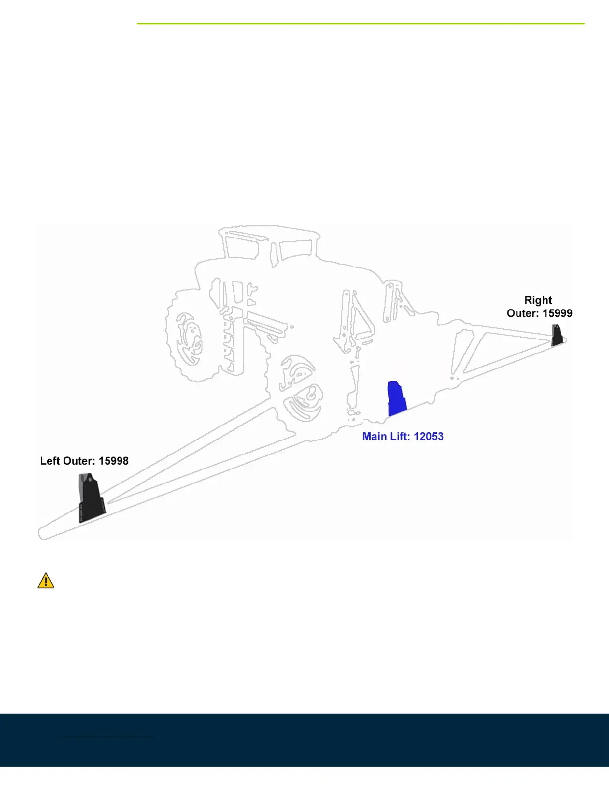
Eachsensorhasaserialnumberstampedonthesensorhousing.
ApplyalightcoatingofthesuppliedPermatexAnti‐seizegreasetoallthreadedpartsuponinstallation.
Figure15:SensorSerialNumberArrangement
TheMAXSensors(E07)aremountedinthepositionsshowninblack.
1. Thesensorbracketshouldbeorientedforward(aheadoftheboom).
2. Typically,thebestmountinglocationfortheouterwingsensorbracketswillbeneartheendoftheboom
tips,approximatelytwofeet(0.6m)
fromtheend.
3. MounttheMAXsensors(E07)intothesensorbracketswiththelowestserialnumberontheleftsideand
thehighestserialnumberontherightside.Runthesensorcablethroughholeinthebackofthebracket.